


 Español (pdf)
 Articulo en XML
 Referencias del artículo
 Enviar articulo por email
 Citado por SciELO
  Similares en
SciELO
Similares en
SciELO 
 Permalink
INTRODUCCIÓN
The use of steel pipe in industrial plants is of vital importance has been considered the vein of the petrochemical industry, refinery, power plant among others, it constitutes an approximate 40 % of the cost of the material in a plant [1]. As non-renewable resources reduce, regions of countries and companies that use oil and gas are increasingly dependent on imports from various parts of the world [2]. Oil industrialization has divided into three micro-processes: Up-Stream, Down-Stream and Mid-Stream, with the latter two processes generating the highest economic margin [3].
A brief review of the scientific literature on pipeline simulations with flexible configuration for hydrocarbon transport has presented below. Rao et al. [4] performed a piping configuration study for the single process unit system upturn. The authors developed the analysis using specialized software, between the process piping and pressure vessel connections, according to ASME B31.3. Expansion loops and spring supports has used in the piping system at point locations obtaining greats stress reduction and increased flexibility of the system. A 6" diameter pipe, SCH 40, ASTM A106 Gr.B was used its operating temperature and pressure of 250 °C and 14.5 kg·cm-2, respectively this value represent a 70 % design when implementing expansion loops.
Jamuna et al. [5] studied the design and analysis of supported piping systems using CAESAR-II software. It has been showed that the piping flexibility of a process system depends on factors such as pipe routing, pressure, temperature, and support location. The authors mention that the use of expansion joints provides a smaller displacement compared to hangers. For the analysis, 8" size pipe, SCH STD, 100 mm insulation and temperature flows of 540 °C were used for steam transport, obtaining in a first analysis 31.7 % value in stresses with the application of hangers and a sustained load rate of 20.8 % with expansion joints, the main use originates when the system does not have enough space to perform the piping configuration, therefore, the use of these is recommended as well as their useful life is less than 2000 cycles.
Akhilesh et al. [6] performed a stress analysis in piping of a pumping system for a process facility. The authors previously developed the installation of the pumps, a static and dynamic analysis for the optimum performance of piping, equipment, among others, to ensure the integrity of the environment and safety of operational personnel. Thermal expansion loops were used at the inlet and outlet of the pumps to reduce the loads on the nozzles of the equipment, resulting in a ratio of 52.2 % which is within the allowable stresses mentioned in the ASME B31.3 code. Lu et al. [7] conducted a study of the analysis of pipes, flanges and tanks for transport and storage of liquefied natural gas (LNG). The authors used a safety factor of 1.5 for the fluid transport design, where at the minimum contact with air, the fluid becomes an explosive detonate of 5 to 15 % before a fire source. SS304 stainless steel tubing was used, with an operating temperature and pressure of 140 °C and 1 MPa with an allowable stress of 137 MPa the pressure results using L and Z type configurations between equipment connection are 174.32 and 153.12 MPa, respectively.
Verma et al. [8] determined a 3D modeling design for a closed-loop, high-pressure, high-temperature helium gas facility. The facility was designed to test several gas-cooled mock-ups, producing considerable thermal deflections and expansions in the piping system. The authors used loops in the course of the piping system in order to understand the operation and control safety factors. A pressure of 10 MPa, temperature of 450 °C and a mass flow rate of 0.4 kg-s-1, were used for the design. The results obtained were a minimum available stress of 29 % and displacements of 9.8, 19.72 and 21.76 mm in the x, y, and z directions, respectively, in the heater outlet line of the loop.
Saha [9] conducted a study on the static interaction between primary and secondary systems comprising structure and piping equipment. The study was performed with an analysis of coupled elements (piping, structure equipment), developing a reliable, realistic, and safe design approach method. For the development of the analysis a numerical simulation method was presented for its validation applied in a real case. A 24" outside diameter pipe was used, with a wall thickness of 12.7 mm connected to two equipment nozzles, with a stiffness in the support springs of 2000 N·mm-1 The results between the composite and grouped system models had a maximum error of 23 %.
Zahid et al. [10] studied the methodology for flexibility analysis in process piping. The efficiency of an industrial plant depends, to a large extent, on its capacity to transport fluids through the piping systems. The authors carried out an investigation of a heat exchanger for reducing dimensions in the expansion loops and consequently saving pipe supports. They used stainless steel pipes ASTM A312-TP316L, a design pressure of 420 MPa, temperatures between 170 and 250 °C between the recirculation pumps and the heat exchanger, placing guide and stop supports in the pipes, obtaining results in stresses that are below the limits that represent between 31 and 46 % respectively.
Shehadeh et al. [11] studied the optimization of thermal expansion loops in piping using ASME B31.3. Long length pipes operating under high temperature conditions tend to expand significantly, which represents the creation of expansion loops these require extra space, supports, bends, elbows, bends, negatively affecting the design cost. The authors carried out the study of a 600 m long gas pipeline in a 24" diameter pipe at a temperature of 85 °C that transports liquid butane, the preliminary design has made in Pipe Data software, and its validation in CAESAR-II software, obtaining the following results, in the most critical case of thermal expansion, a reduction in the size of loops, from 8000 to 2000 mm, obtaining an approximate saving of USD. 30000 (four loop).
Saputra et al. [12] performed piping analysis of the ballast system of 24 tugboats. The ballast system in ships, especially in tugboats, serves to help stabilize the ship so it can sail safely. The authors conducted the study to determine the magnitude of sustained and circumferential stress produced in the ballast pipes. The modeling of the piping system and analysis was performed in AutoPIPE software, taking as reference the ASME B31.3 standard, the operating data used for the analysis were seawater at normal temperature of 30 °C and ballast working pressure 72.52 psi, obtaining that the resulting stress value is below the allowable of the material A53-B (galvanized), which is equal to 20 ksi.
The objective of the present study is to analyze the flexibility in the piping network of a hydrocarbon pumping system in a real rigid and flexible models to determine the stresses produced in its operation. This document presents four sections. First section cover aspects of pipe networks, the stress analysis, and the art state. The second section shows the materials and methods used to develop the study, focusing on the flexibility mathematical models to achieve the results. The third section analyzes the results using simulation software by means of comparative tables and graphs. Finally, in the conclusions section the results are mentioned to determine which pipe arrangement is the most appropriate, complying with the parameters established under the respective standard.
MATERIALS Y METHODS
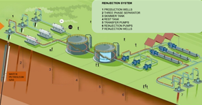
The oil exploitation and natural gas depends on the location of the fields and the various techniques used for the crude extraction of "black gold" products. A production facility is the set of one or more facilities within which hydrocarbons from one or more fields had processed to separate them into oil, gas and water [13]. The transfer of hydrocarbons from one place to another is carried out through steel pipes (overhead or buried) by means of pumping or compression stations. Fig. 1 shows the oil's production process when extraction from an oil and gas facility begins.
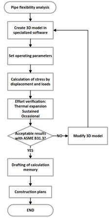
The methodology of the design procedure is to perform a configuration within safe and economic parameters, the preliminary systems creation for the development of the flexibility analysis allows to verify the different stresses and displacements in order to detect possible failures in the future [14]. Fig. 2 provides important information about the procedure that was considered to carry out the analysis in pipes.
Among the important design considerations of a piping system, in addition to its good performance in terms of operability and efficiency, its cost must be considered, and this successively depends on the dimensions of the line (length, diameter and wall thickness), in addition to the material used for its manufacture [15]. According to ASME B31.3 [16], the thickness of straight sections in pipes should determine by the following equation:

For values of t < D/6, the design thickness with internal pressure for straight pipe should not be less than the value calculated according to equation (1). Thickness is determined by the design pressure values P multiplied by the pipe diameter D, the allowable stress values S of the material at the operating temperature are tabulated in Table A-1 of ASME B31.3 [16].
The allowable expansion stress is the limiting value of the material stress at the operating temperature [17]. The following is the equation for determining the allowable stress at system temperature [11][18].


And 

For the result of allowable expansion stress SA, it is determined with the sum of values of allowable stresses at the minimum temperature of metal "cold" SC, allowable stress at the maximum temperature of metal "hot" Sh, determined in Table A-1 of ASME B31.3 [16] and multiplied by the factor of stress interval f (number of cycles of the system).
The circumferential stress in pipes, is caused by internal pressure, and is calculated by Barlow's formula [19] for thin-walled cylinders. Equation (4) must fulfill that SHOOP must be less Sh allowing the pipe not to expand in the circumferential direction [15].

For the sustained case, it allows the study of the sum of longitudinal stresses SL, in any element of a piping system that are produced by sustained loads such as material self-weight and point or distributed forces, applied moments, internal pressure and isolations [10]. Equation (5) must comply with the fact that Sh must be greater than SL [12], thus ensuring that the pipe does not have stresses that cause plastic deformation or failure of the material.}

Briefly for expansion case, it allows the study of pipe expansion and contraction due to thermal variations with respect to the system temperature pipe displacement that were present in plant start-ups or shutdowns [20]. The objective is to ensure that the thermal expansion (SE) value always remains below the allowable stress (SA) in any circumstance of the system operation [21].


This mathematical model allows determining the thermal or secondary stress (SE), it is formed by the sum of the resultant bending stress (Sb) plus the resultant torsional stress, which is dependent on the pipe section modulus (Z).
Prior to their stress analysis, the process pipelines are identified according to the temperature at which the line will be in operation, data that will be determined by the bases and criteria of the project, considering as temperature for the analysis, the maximum operating temperature. The process lines category shows in Table 1 [22].
Table 1: Boundary condition values for the refrigerant
| Diam. | Ferritic material | Austenitic material | ||
| D ≥3” | > 200 °C | < -230 °C | > 166 °C | < -157 °C |
| D = 4” | > 150 °C | < -140 °C | > 124 °C | < -100 °C |
| D ≥6” | > 100 °C | < -90 °C | > 83 °C | < -51 °C |
| D ≥18” | > 750 °C | < -41 °C | > 63 °C | < -28 °C |
To start the pumping system modeling; the process and instrumentation diagram (P&ID) is required, which provides information related to the process plant (pressure, temperature) such as number, size of process lines, name of mechanical equipment and electrical instruments, interconnectivity between areas related to the process flow [23].
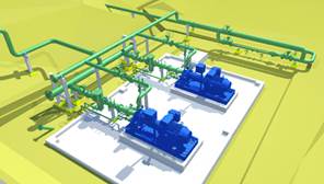
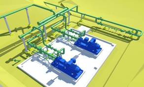
Fig. 3 shows the preliminary design of the pumping system with basic engineering, generally without flexibility, while Fig. 4 shows the pumping system design with detailed engineering, generally developed with flexible design both fulfill the same purpose within an operating philosophy, to be able to transport produced water, This water is stored and sent to the suction heads of the re-injection pumps and these in turn send water with high pressures to the heads of the re-injection wells, in order to increase oil extraction, the system consists of two centrifugal pumps with two suction and discharge nozzles respectively.
RESULTS
After obtaining the premises, values and initial dimensions to be used, according to daily oil production data, the geometric configuration of the pipes is modeled in the design software for its subsequent flexibility analysis, which is performed using the specialized software Bentley AutoPIPE, which allows the development of pipe behavior analysis [24].
For the development of the piping analysis, two preliminary configurations were carried out, the first one has designed with a system without flexibility (A), and the second one with a design with the flexibility (B), which will provide data and results for the selection of a correct and safe design. Next, the results obtained from the simulation are detailed, specifying the points of maximum stress and greater displacement of the piping system in general, as well as the forces and moments acting on the nozzles of the equipment itself, to compare the values obtained with the maximum values allowed by the respective design codes.
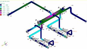
In Fig. 5 and 6, models A and B are shown respectively, from which the analysis of displacements and rotations generated as a consequence of the imposed load conditions has performed, also discarding any situation of interference due to movements of the set of pipes. In general, the spaces between supports for the system allow for minor deflection.

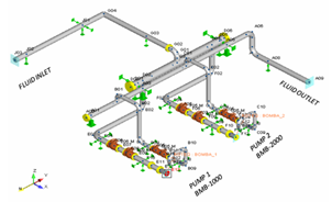
Table 2 shows the nodes with the values of displacement and maximum of the systems rotations, according to the operating pressure and temperature.
Table 2: Maximum displacement values
| System A | System B | ||||
|---|---|---|---|---|---|
| Max. Obtained | Node | Max. Obtained | Node | ||
| Dz (in) | -0.42 | G03 | -0.11 | F02 | |
| Dx (in) | -0.35 | A05 | -0.10 | C01 | |
| Dy (in) | -0.25 | A00 | -0.12 | A00 | |
| Rx (°deg) | -0.69 | G03 | -0.07 | F03 | |
| Ry (°deg) | -0.42 | A06 | 0.05 | E01 | |
| Rz (°deg) | 0.21 | G03 | 0.05 | E06 | |
In Fig. 7 and 8 models A and B are shown respectively, from which the analysis of the sustained and expansion stresses has made, which were calculate using the maximum operating conditions of the piping system in question (pressure and temperature) considered as the most critical scenario, when the two pumps are in operation. In the system A model in Fig. 8, the sustained stresses are analyzed, with a maximum value of 242 % of the allowable in node G04, the expansion stresses. The values obtained are still higher than the maximum values allowed by the ASME B31.3 code, so the system is not in the safe design and operation zone, having to redesign the model for a new analysis.


For configuration model B in Fig. 8, the system analysis is performed, where the stress values in support and thermal expansion are below the allowable values of ASME B31.3 with a ratio (ratio between calculated forces and allowable forces) not greater than 48%, respectively in thermal expansion, the flexible configurations type L and Z allow the system to release stresses when in operation. The analysis of the model ensures that the operational aspects and the configuration of the system constraints or flexibilities, with respect to the material characteristics.
Table 3 shows the stress values for the two systems the location of the nodes and their percentage for the allowable stress. The results report the system safety of against temperatures and approximate cyclic loads in pumping equipment of approximately 7000 cycles, which lead to the development of secondary stresses in the system. For the two piping designs, the maximum values of the nodes in the Hoop Stress case do not exceed the allowable stress limits according to ASME B31.3 these values represent between 20 to 35 % of the allowable stresses at the hot material temperature.
| Stress (ksi) | Max. Stress ratio (%) | ||||
|---|---|---|---|---|---|
| Cases | Node | Calculated (max.) | Permissible (Standard) | ||
| A | Hoop | A08 | 6.937 | 20 | 35 |
| Support | G04 | 48.497 | 20 | 242 | |
| Expansion | O09 | 34.154 | 30 | 114 | |
| B | Hoop | A09 | 3.990 | 20 | 20 |
| Support | F12 | 16.353 | 20 | 73 | |
| Expansion | C15 | 14.459 | 30 | 48 | |
Fig. 9 shows all the values of the sustained stresses found in systems A and B, which allows understanding how the stresses act on each node and system has about 110 and 160 nodes, respectively. The results for system A have stress peaks that exceed the admissible stress of 20 ksi recommended by the B31.3 standard, while for system B the values of the nodes that make up the system are below the standard, having as maximum stress a node of 73.3 %, allowing the system to be in the safe design zone.
The piping configuration of system A, generates large concentrations of loads of individual forces and moments, obtaining 2 to 3 times the permissible of the standard and which was transmit to the suction and discharge nozzles of the pump, so they do not meet the conditions of API 610 [25]. For the case of system B configuration, the loads of the equipment nozzles are lower where the values obtained are lower than the permissible of the standard these results are obtained because the design of the configuration, spacing or distribution of the supports is adequate in order to ensure the mechanical integrity of the same, for the analysis a friction factor of 0.03 was used, between support with pipe, application of guides, Teflon pads and good engineering practices.
Rao [4] states in his research that the use of loops or pipe loops in the piping system for the case study was determinant, the use of these pipe arrangements avoids the use of springs, brakes in the supports as thermal expansion joints, which help for special cases, taking into consideration that they are of great value as delicate in their operation. In addition, Shehadeh [11] designs a preliminary piping system in Pipes Data Software, and its validation in Caesar-II software, for the case study the results obtained in the analysis have performed according to good engineering practices and its flexibility validation was performed in the specialized software AUTO PIPE, having punctual corrections in the location of support points.
CONCLUSIONS
The study of the piping system allows the application of the fundamental concepts in the analysis of flexibility in pipes, based on the results found, the following conclusions were present:
In the designs of pipe systems A and B, the analysis was developed obtaining for a first analysis of support and expansion values of 48.49 and 34.15 ksi, respectively, in the nodes, which represent approximately 200 to 300 % of the permissible standard, for a second analysis, the design of the model was improve (pipe-supports), thus obtaining values of lower stress as 16.3 and 14.4 ksi in the most critical nodes both in sustained and thermal respectively, values that are within the permissible of the standard ASME B31.3.
The analysis allows observing the behavior of the supports with the pipes case studies A and B, Teflon pads of 2- or 3-mm thickness should be placed in all the contact surfaces, values that allow the software to have a value of 0.1 as friction constant, the pads allow reducing the thermal loads of the system between 20 and 80 %. The analysis allowed a better distribution and selection of the supports for the system design.
With the application of 7000 pump cycles, operating temperatures of 150 °F and installation temperature of 70 °F the temperature differential is 80 °F which generates thermal expansion, that to the case study has been absorbed by the Z and L type expansion loops in the system piping, allowing to avoid the installation of thermal expansion joints.
In the analysis of the nozzles, the ratio data in system A in suction and discharge are 8.91 and 5.58, respectively system B the pipes meet the criteria of ASME B31.3 the ratio data in suction and discharge are 0.15 and 0.5, respectively, data that do not exceed the 1 ratio of the allowable load according to API 610.

