


 Español (pdf)
 Articulo en XML
 Referencias del artículo
 Enviar articulo por email
 Citado por SciELO
  Similares en
SciELO
Similares en
SciELO 
 Permalink
1 Introduction
For more than a decade, the subject of antenna polarization has generated great interest. The definition can be complex as radiating and receiving structures respond differently, both in frequency and angle between the incident and transmitted wave (Thornton & Huang, 2013). When antenna patterns are taken in the usual way, the Ludwig definition is commonly used. In Ludwig (1973) the definitions of co-polarization (reference polarization), and cross polarization applied to linearly polarized antennas are presented. An antenna radiation in a specified polarization, which is called reference polarization; whereas radiation in the orthogonal polarization is known as cross-polarization (Aznar et al., 2004). In addition, Ludwig’s definitions are clarified using different polarized reference sources located linearly in different orientations (Aboserwal et al., 2018). The low cross polarization generates a distribution of a highly symmetric field in the aperture, however, it is difficult to achieve a reduction of cross polarization over a wide bandwidth.
Alternatively, a wideband approach for significantly reducing the cross-polarization levels of standard-gain horns, for an X-band standard from 6.5 GHz to 18 GHz, applying filter screens has been proposed (Kuloglu & Chen, 2013). In addition, to improve the cross-polarization performance, two pairs of arc-shaped slots have been added to the ring slot antenna, for a circular aperture antenna with differential feeding (Chen et al., 2017). Also, a defected ground structure with integrated square patch has been proposed Kumar et al. (2015). The defect is deployed surrounding the element maintaining a considerable spacing from the patch boundary. Moreover, the undesired cross polarization of the reflector antennas, can be reduced with a circular-rim (Pour & Shafai, 2012). In this paper, we propose the analysis and simulation of a circular waveguide with the addition of metallic rings as elements to improve the radiation pattern in the 3−7 GHz band. The simulation of the antenna has been done with a CST frequency domain solver (Dassault Systemes, 2018). Finally, to validate the concept, metallic square rings are added in the design of a patch antenna at 5.8 GHz.
2 Modeling a circular waveguide with metallic rings
2.1 Circular waveguide
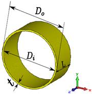
The main parameters of a circular waveguide are the length of the enclosing metallic wall (𝐿), and the inner diameter of the circular waveguide ( 𝐷 𝑖 ). The thickness of the waveguide (𝑡) does not affect the bandwidth, therefore a standard waveguide WR-229 can be used, which thickness is 1.63 mm.
The cutoff frequency of the circular waveguide is determined by the equations (1) y (2) (Balanis, 2012), where 𝜌 is the radius of the waveguide, 𝜒 𝑚𝑛 are the roots of Bessel functions and 𝜒′ 𝑚𝑛 are the roots of the derivative of the Bessel functions.
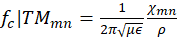

Taking into account that the waveguide is modeled as PEC (perfectly electrical conductor), the dominant circular waveguide mode is 𝑇 𝐸 11 (Pozar, 2009), and the following mode is 𝑇 𝑀 01 . The cutoff frequencies of these modes can be obtained with equations (1) and (2).
For a cutoff frequency of 3.25 GHz for mode 𝑇 𝐸 11 , it can be deduced from (1) that the radius of the waveguide must be 𝜌= 27.03 mm. Table 1, shows the values of the cutoff frequencies for the different modes of the circular waveguide with this radius. The geometry of the circular waveguide is depicted in figure 1, with an inner diameter 𝐷 𝑖 = 54.06 mm (0.65 𝜆), an external diameter 𝐷 𝑜 = 57.32 mm (0.69 𝜆), and a length 𝐿= 25 mm, where 𝜆 is the free-space wavelength at the design frequency (𝑓= 3.625 GHz).
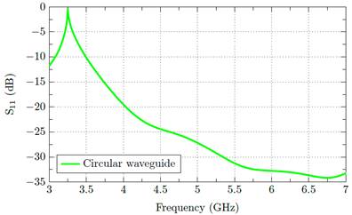
To validate the performance of the circular waveguide, the 𝑆 11 parameter is simulated. As can be observed in figure 2, the result show a good matching (S 11 <−10 dB) from 3.5 to 7 GHz.
2.2 Analysis with metallic rings
As the circular waveguide has a poor cross polarization, three possible solutions have been considered to improve the cross polarization (Santillan, 2017). The first solution is to add a metallic disk as shown in figure 2. After an optimization process the value of the external diameter is 𝐷 1 = 90.42 mm.
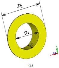
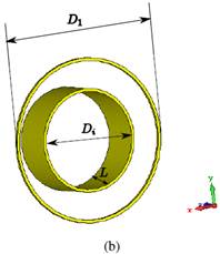
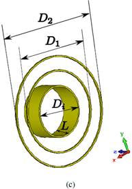
Figure 3: Proposed solutions to improve cross polarization in a circular waveguide. (a) Metallic disk. (b) Metallic ring. (c) Two metallic rings.
The second solution is to place a metallic ring around the circular waveguide (see figure 2). The optimized dimension of the external diameter ring is 𝐷 1 = 90.42 mm with a thickness of 1.63 mm.
A third solution is to place 2 rings around the circular waveguide as indicated in figure 2. The optimized dimensions of the rings are: an outer diameter of 𝐷 2 = 122.48 mm, and an inner Diameter 𝐷 1 = 90.42 mm. Note that the thickness of the rings has the same value as the second solution.
3 Simulated results and validation with a patch antenna
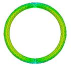
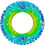
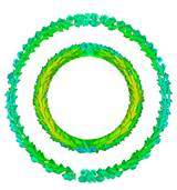
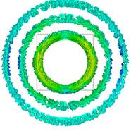
Figure 4: Surface current distribution at the design frequency (𝑓= 3.625 GHz). (a) Circular waveguide. (b) Metallic disk. (c) Metallic ring. (d) Two metallic rings.
Figure 4 a), b), c), d) shows the surface current distributions of the proposed solutions. It is clear that the currents are concentrated around the internal diameter 𝐷 𝑖 of the metallic disk (see figure 3). a), b), c) Figs. 3 and 3 show the total current in one and two rings, respectively. Observe that the distribution of the current in the circular waveguide is the same as in the metallic ring, while in the configuration of two rings, the current densities have the same direction in the internal radius, and in the outer radius the currents are opposite and small. In figure 5, a), b), c) the simulated E-field distribution of the circular waveguide with metallic rings is presented. As can be observed, the electric field distribution in the metallic rings is symmetric, which gives an improvement in the radiation diagram (figure 6).
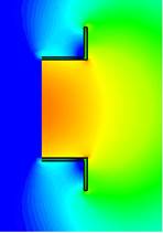
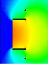
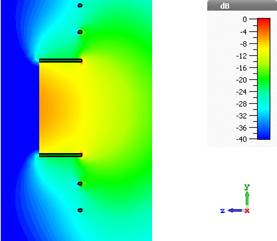
Figure 5: Electric Field distribution at the design frequency (𝑓= 3.625 GHz) of the circular waveguide. (a) Metallic disk. (b) Metallic ring. (c) Two metallic rings.
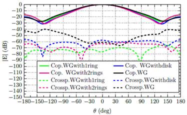
Figure 7: Copolar (Cop.) and cross-polar (Crossp) components of the radiation pattern in the xz plane at 3.625 GHz for the proposed configurations.
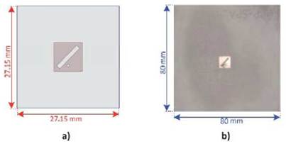
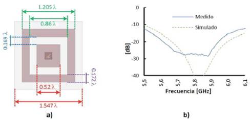
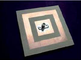
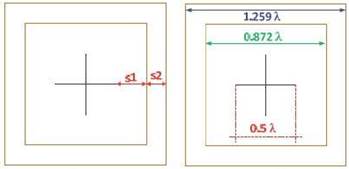
Figure 11: Electrical dimensions of the patch antenna with two metallic rings (Méndez et al., 2013).
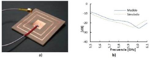
Figure 7 shows the copolar and cross−polar components of the radiation pattern on the xz−plane at 3.625 GHz. As it can be seen, the cross-polar component is 50 dB below the copolar component within the main beam.
3.1 Patch antenna with a surrounding metallic ring
A patch antenna type is the thinnest element for circular polarization (Méndez, 2015). For implementation it is considered an antenna with dimensions as shown in figure 8.
The results of the large antenna have a great similarity but increasing the size adversely affects the behavior of the diagram and polarization, so it is necessary to redesign.
3.1.1 Design modifications in the path antenna
Considering that electromagnetic band gap (EBG) structures are used to suppress the effects of surface waves (Cho & Lee, 2010), a metallic ring surrounding the original small ground plane is inserted, as can be seen in figure 9. The behavior of this square ring is similar to the one presented previously for circular rings. By varying the width of the metallic ring, and the distance from the plane, a good matching level is obtained (see figure 9 (b)).
A prototype of the path antenna with a surrounding metallic ring was fabricated and measured. A picture of the fabricated patch antenna is shown in figure 10.
As a second improvement, the ring thickness of figure 10 is replaced by another 2 thinner rings. The new dimensions are shown in figure 11. With the variables 𝑆 1 and 𝑆 2 we can tune the resonance frequency. If the spacing between the inner ring and dipoles is less than 0.20𝜆 there is a frequency shift of 1% (approximately). For values of 𝑆 1 of 0.40 𝜆 the bandwidth is increased by about 10% compared to the bandwidth of the dipoles without rings.
To improve the matching level, a circular groove (3 mm of diameter and 0.2 mm of width) located in the ground plane around the inner conductor can be introduced. The manufactured antenna with two surrounding metallic rings is shown in figure 12 (a). By replacing the large ring by 2 thinner rings, a bandwidth of 7.6% was obtained. In addition, a good matching level ( 𝑆 11 <-20dB) in the whole 5.5 − 6.10 GHz band (see figure 12 (b)) was obtained.
4 Conclusion
In this work, the improvement of cross polarization were obtained through metallic rings around a microwave antenna. An open-ended circular waveguide was used as the primary feed for the metallic rings. The simulated structures provide a good cross-polar level (better than -50 dB) with a good matching level (S 11 <−14 dB) from 3.5 to 7 GHz. To verify the design, a patch antenna with surrounding metallic rings was presented. Measured results show an optimum coupling, within a wide range of frequencies from 5.5 to 6.10 GHz.

