


 Español (pdf)
 Articulo en XML
 Referencias del artículo
 Enviar articulo por email
 Citado por SciELO
  Similares en
SciELO
Similares en
SciELO 
 Permalink
INTRODUCCIÓN
Two-phase flow and boiling phenomena are used in a variety of processes and applications, such as refrigeration systems, air conditioning and heat pumping, energy conversion and heat exchange systems, thermal chemical processes, cooling of electronic components of high power, among others [1]. The study of the boiling process in domestic, commercial, and industrial refrigeration applications has increased in recent years, however, most of these studies have emphasized round pipes and research on other types of geometry is almost nil. Square pipes in the transport of fluids are important in installations with few irregularities and for long lengths.
Compliance with environmental regulations requires the use of environmentally friendly refrigerants. Refrigerant manufacturers are currently pushing their efforts in the development of new low-GWP refrigerants, which can replace common HFCs [2]. A natural refrigerant (R600a) not only has a value of zero in ODP and very low GWP, but it also has other thermodynamic advantages over other refrigerants, such as a low liquid density than most HFC's [3], [4].
With the phasing out of conventional refrigerants, isobutane (R600a) emerged as the main alternative in the refrigeration industry. Hydrocarbons, the class of refrigerant to which R600a belongs, are viable substitutes as they possess favorable cooling thermal properties. However, the investigation of this refrigerant goes beyond its use alone; its compatibility and performance with compressor oils are currently being investigated [5].
The high latent heat of the R600a requires a smaller compressor size to provide the same capacity [6]. Due to its good cooling performance and environmentally friendly characteristics, R600a has been used as an alternative refrigerant in heat transfer applications such as refrigerators, freezers, and heat pumps, although it is flammable [7].
Flow boiling in refrigerants within the tube in macroscale or conventional channels can be classified according to nucleate boiling (related to the formation of vapor bubbles on the surface of the tube wall) and convective boiling (related to conduction and convection) [8], [9].
Copetti et al. [10] carried out an experiment to investigate the heat transfer of the boiling flow for R600a in a tube with an internal diameter of 2.6mm. They found that the heat transfer coefficient increased with heat flow at low steam qualities.
Unlike experimental studies, Computational Fluid Dynamics (CFD) simulations are better able to provide detailed information on local hydrodynamics and two-phase boiling flow heat transfer, therefore it can be used as a tool. of additional research [11]. The difficulty of flow boiling simulation is mainly due to two challenges: the interface tracking algorithm and the phase change model. The domain flux of surface tension makes monitoring difficult because the interfacial curvature is inversely proportional to the dimension [12].
Ferrari et al. [13] conclude that, the velocity of the bubble in a square channel is always larger than that in a circular channel. This happens because the cross-sectional area occupied by the liquid film in a square channel is larger.
Over the years, various methods have been developed for the study of phase change [14], [15]. The Lagrangian or Eulerian method is used to evaluate the interface. In Lagrangian methods, the interface is represented by mesh faces, which allows an accurate evaluation of the normal gradient of the interface [16], [17]. However, it is expensive to trace complex interfacial deformation in transient problems using a moving mesh with Lagrangian methods. In Eulerian methods, the interface geometry is reconstructed from a color function that is used to track phases, such as the volume fraction in fluid volume (VOF) methods. This allows convenient monitoring of complex interface deformations [18], [19].
The objective of this research is to determine numerically by ANSYS Fluent, the boiling process of the natural refrigerant R600a that circulates inside large square pipes.
METODOS Y MATERIALES
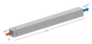
For this study, a square pipe section is considered, 1.5 m long with a variable side distance starting from 20 mm to 30 mm, these dimensions are found in the Ecuadorian industry. In Fig. 1, the dimensions of the pipe to be simulated can be seen. On the other hand, it is essential to clarify the material of the pipe, it is commercial steel distributed in the Ecuadorian industry.
The analysis is carried out for various types of square tubes, with different side lengths. However, the mass flow for R600a is modified with values of 300 and 400 kg/m²·s, in addition, the heat flow is also a variant in this study, it is analyzed for values of 10, 15 and 20 kW/m².
It has already been mentioned, the fluid to be used is R600a (Isobutane) refrigerant, which is a natural refrigerant and very friendly to the environment and completely safe. The boiling process is carried out at a temperature of 8 °C, where the fluid enters in a state of saturated liquid and the output is a mixture of liquid with steam at the same entering temperature.
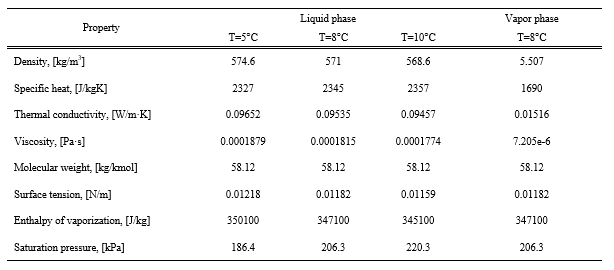
Table 1 shows the thermophysical properties of R600a at saturation temperature, for the liquid phase as well as for the vapor phase.
Numerical models
The term boiling is used to describe the situation where the temperature is higher than the temperature at the boiling point. The energy is transferred directly from the wall to the liquid, this heat will cause the temperature of the liquid to increase and generate steam.

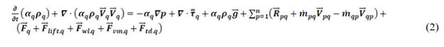


In the Fluent ANSYS the boiling models are developed in the context of the Eulerian multiphase model. Multiphase flows are governed by conservation equations for the continuity of the phase, momentum and energy, these equations are shown below, respectively.
Where, V ⃗_q is the velocity of phase q. And m ̇_pq characterizes the mass transfer from phase p to q, m ̇_qp is the transfer of mass from phase q to p, and you can specify these separately. τ ̿_q is the stress tensor for phase q, u_q and λ_q is the shear and apparent viscosity of phase q, F ⃗_q is a force external to the body, F ⃗_(lift,q) bearing force, F ⃗_(wl,q) a wall lubrication force, F ⃗_(vm,q) is a virtual mass force, F ⃗_(td,q) is a turbulent dispersion force and R ⃗_pq is the interaction force between the phases. V ⃗_pq is the speed between the phases [22].
These fundamental formulas are the basis of the Rensselaer Polytechnic Institute (RPI) models, the phenomenon is modeled by the nucleate boiling of RPI exposed by Kurual and Podowski [23].
The total heat flux from the wall to the liquid is divided into two components, called convective heat flux and evaporative heat flux.
The heated surface of the wall is subdivided into, area A_b which is covered by nucleation bubbles and a portion (1-Ab), which is covered by fluid.
The convective heat flux qC is expressed as:

The evaporative flow qE is given by equation 7:

Where, h_c is the heat transfer coefficient for a single phase, T_w and T_l are the wall and liquid temperatures, respectively. V_d is the volume of the bubble based on the exit diameter of the bubbles, N_w is the density of the active nucleated site, ρ_v is the density of the vapor, h_fv is the latent heat of vaporization and f is the exit frequency of the bubble.
The κ-ε (kappa-epsilon) turbulence model is one of the most widely used in the field of CFD simulation, the two-equation model has presented robust results in the turbulence field for both kinetic energy and energy dissipation, kappa, and epsilon, respectively.
Within this two-equation model are other submodels, such as standard, RNG and realizable. All three could be used for the simulation of the boiling process, however, the RNG model was chosen for its great adaptability to the fluid and working geometry. On the other hand, this model was derived using a certain statistical technique normalization group theory, it is like the standard basic model, although, it includes certain improvements.
For the transport equations involving the κ-ε RNG model are described below. Equation 8 represents the turbulent kinetic energy and equation 9 is the turbulent dissipation energy.
In the equations, G_k represents the turbulence kinetic energy production due to the average velocity gradients. G_b is the generation of turbulence kinetic energy due to buoyancy. The quantity Y_M symbolizes the contribution of the fluctuation dilation to incompressible turbulence to the overall dissipation rate. C_1ε, C_2ε and C_(3ε )are constants. σ_k and σ_ε are the turbulent Prandtl number for k and ε, respectively. S_k and S_ε are user-defined source terms [22].
RESULTS AND DISCUSSION
In the simulation process, meshing the convergence of the solution is extremely important, since, with a good mesh size, the transport equations for energy, continuity, boiling, momentum and turbulence will be obtained, they can be appropriately discretized inside the analysis geometry.
In Fig. 2, the mesh made to the square steel tube can be seen, as well as the size of the mesh, which for this investigation is ideal.
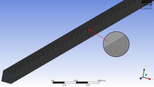
Although the mesh looks perfect and does not show irregularities, it is essential to carry out a meshing convergence study, for this, the computational tool, skewness, is used, which details how much is the minimum value required for the mesh to work and converge to any type of CFD simulation. Where a value of 0 represents that all the elements are equilateral, while, for an interval between 0-0.25 the mesh is excellent and for values that are in 0.25-0.5 the mesh is good.

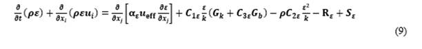
Fig. 3 shows the mesh convergence for the analysis geometry after performing a meshing technique, under the size regulation procedure. Likewise, it is appreciated that the greatest number of elements are between 0-1, therefore, the meshing is excellent for any simulation process with Fluent.
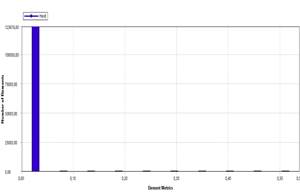
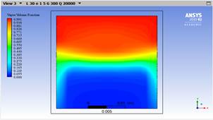
Fig. 4a indicates that, the boiling process inside a square tube occurs from the wall to the inside of the tube, however, it is visualized in a plane in the central part of the pipe, the red part represents the refrigerant vapor, while the blue part is the liquid phase. The steam is only located in the upper part, this is because the liquid has a higher density than the steam and for this reason only steam is seen in the upper part. On the other hand, Figure 4b represents the progression of the boiling process inside the square tube, this time in a 3D graph, with 150 mm divisions in the length.
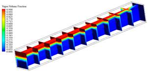
Figure 4: Boiling for case A, 0.030 m, thickness 1.5 mm, mass flow of 300 kg/m2·s and heat flow of 10 kW/m2, a) 2D and b) 3D
Although the simulation for case A solved the boiling problem inside a square tube, it is important to compare these results with other simulations, where one of the process variables is modified.
The boiling process is given by the application of heat flow that enters through the walls of the tube, this begins with 10 kW/m² and is modified twice, both for 15 and 20 kW/m², these values were chosen, since which are very close to the theoretical value calculated for the boiling phenomenon. However, the rate of entry of refrigerant into the tube remains fixed.
In Fig. 5, the boiling in the central part of the square tube is shown, for the three variations of heat flow. It is visualized that, in the central axis of the tube, for heat flow 10 kW/m2 the phenomenon is not present yet, however, for 15 kW/m2 the boiling occurs in the last third of the pipe. Finally, for the highest flux of 20 kW/m2 the process is exhibited upon reaching the center of the full length of the tube.
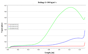
Fig. 6 compares not only the change in heat flow, but also the variation in the input mass flow. This figure shows the behavior of the boiling phenomenon under two changes, the mass flow, and the heat flow.
For higher mass flows the boiling does not stand out, as for the lower mass flow, however, there is a phase change of 35 % for the maximum heat flow of 20 kW/m2, almost half of that achieved with the mass flow 300 kg/s·m², so low flow rates are recommended to support the boiling process. Furthermore, it must be considered that the speed set guarantees a turbulent flow regime.
The results shown in the previous figures indicate how the boiling phenomenon occurs, however, these have only been simulated for half of case A, the other half corresponds to the change in the thickness of the square tube. In Fig. 7 the boiling for this thickness of pipe can be seen.
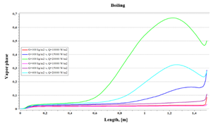
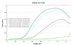
Fig. 8 represents the boiling phenomenon for a 25 mm square tube with thicknesses of 1.5 and 2 mm, with a constant mass flow of 300 kg/s·m², and heat flows that vary from 10 to 20 kW/m2. The lines between cuts symbolize the simulations for the 1.5 mm thickness and the solid lines for the 2 mm thickness.
It can be seen in the same figure that for higher heat fluxes the steam quality is higher than for low fluxes. Likewise, for heat flux of 10 kW/m2, the boiling is similar and has no variation. It should be considered that for higher heat fluxes a characteristic variation of the phase change is shown.
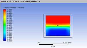
In Fig. 9, the boiling for heat flow of 10 kW/m2, mass flow of 300 kg/s·m² and side modification of 30, 25 and 20 mm is visualized, Figures 9 a, b and c, respectively.
For case A, the boiling process has reached 8.5 % as steam at the outlet, in case B the vapor phase reached 21.82 % and in case C it is 70.89 %. This shows that if the side decreases the boiling effect increases.
CONCLUSIONS AND RECOMMENDATIONS
At the end of the numerical-thermal study of the boiling process in cured tubes, the following conclusions were reached:
The heat flow that is needed to carry out the boiling phenomenon inside a square tube is only 3.25 % of what is required for total evaporation, which is why it was chosen to simulate with heat flows that exceed this percentage up to 7 % which is a flow of 20 kW/m².
The mass flow was placed according to the turbulent flow study for both the analytical and numerical part, a flow of 300 kg/s·m² was designated, because, with this, the flow and the Reynolds number are always in regime turbulent. In addition, 33 % was added in the rate of entry and observe how the boiling effect is modified inside the tube.
For the simulation carried out on two tubes with a side 25 mm, thickness 1.5 mm, heat flow 15 kW/m². with modification of the mass flow of 300 kg/s·m² and after 400 kg/s·m², qualities of steam at the outlet of 72.75 and 51.15 %, respectively, which indicates a reduction of 29.7 % in the vapor phase due to the increase in velocity. However, by increasing 0.5 mm in thickness, the decrease of 2.15 % in the vapor phase is determined for the mass flow of 300 kg/s·m² and 3.65 % in the simulation with the increase in flow to 400 kg/s·m².
Square pipes are frequently used in the refrigeration industry; however, the length of these pipes corresponds to very large air conditioning processes. therefore, it is recommended to use this study for very large cases.

