


 Spanish (pdf)
 Article in xml format
 Article references
 Send this article by e-mail
 Cited by SciELO
  Similars in
SciELO
Similars in
SciELO 
 Permalink
Forma sugerida de citación:
Alarcón, A.; Cadena, A.; Villao, F. (2017). «Design of a Tsunami Early Warning System for Ecuador based on Satellite Terminals». INGENIUS. N. 18, (julio-diciembre). pp. 83-90. ISSN: 1390-650X.
1. Introduction
The 2004 Indian Ocean earthquake and tsunami motivated the improvement of the Tsunami Early Warning Systems across the world [1]. The 9.0 earthquake of March 2011 and the resulting Tsunami at the Japanese coast demonstrate the importance of an Early Warning System when a Tsunami is generated near to the coast [2]. DART (Deep-ocean Assessment and Reporting of Tsunamis) system developed by the NOAA (National Oceanic and Atmospheric Administration) has proven to be robust and reliable to detect Tsunami waves at high sea [3]. The DART system is composed basically by a group of Bottom Pressure Sensors each one communicates with an acoustic data link to a surface buoy. The generated data is send by a satellite data link from the surface buoy to a Tsunami Warning Center [4].
Ecuador is located on a place characterized by great seismic and volcanic activity [5]. Near to the Ecuadorian shore is located the Pacific Ring of Fire that could generate powerful earthquake followed by a Tsunami event. In the 20 century there were important seismic events like the 1906 earthquake and Tsunami that impacted the coast of Esmeraldas, Ecuador [6]. The main seismic threat for Ecuador is the subduction process of the Nazca plate beneath the South American Plate. There is a great depression on the Ocean floor 50 Km offshore from the Ecuadorian coasts due to subduction process. Earthquakes with magnitudes bigger than 6.7 whose epicenters are close to the coast line or in the Ocean floor are considered Tsunami triggers. The INOCAR, the Oceanographic Institute of the Ecuadorian Navy, has deployed two DART Tsunami buoys manufactured by MESEMAR, near to the coast of Ecuador, linked with the Pacific Tsunami Warning Center and INOCAR installations.
INOCAR is continuously monitoring the buoys readings and in case of a major Tsunami event generates a warning for the population. It also gives regular technical support to the installed buoys. Recently the Ecuadorian 2016 earthquake with a moment magnitude of 7.8 generated a small local Tsunami event registered clearly by the DART buoy system and INOCAR local sea sensors. This Tsunami took less than 10 minutes to arrive to the coast of Esmeraldas. The first instrument that registered the Tsunami waves after the earthquake was the Dart Buoy two minutes later; this demonstrates the reliability of the system and the risk of a major Tsunami event at the coast of Ecuador [7]. Under this hypothetical scenario where a local major Tsunami is generated and would take less than 10 minutes to arrive to the Ecuadorian coasts, we propose an automatic Tsunami Early Warning System based on Satellite terminals and open source hardware/software platforms.
Recently open source hardware and software have become very popular across the applications developer community due to its low cost and available information in the cloud. Examples are the embedded system platforms like Beaglebone [8] or Raspberry [9] that are continuously improved by the developer’s community. One of the more popular hardware platforms is the Arduino microcontroller board due to its simplicity, reliability, low cost and free access to source codes and bibliographical information from the cloud [10]. Also Its low cost and low power satellite terminals make them suitable for satellite data links in applications where hardware space and power consumption are critical.
Satellite service providers like Inmarsat, Iridium and Globalstart have launched to the market small satellite terminals for ground, sea and air M2M applications [11]. An important example of their application for tracking a vehicle was the accident of the Malaysia Airlines flight MH 370, the satellite terminal installed in the aircraft had a relevant role to establish the potential crash site at the Southern Indian Ocean [12]. The low power consumption of this kind of satellite terminals allows ultracapacitors energy storage solutions powered by solar panels [13]. The main advantage of the ultracapacitors in relation to conventional lead acid or Litium-Polymer batteries is their durability, which could be more than five years therefore reducing the maintenance cost [14].
2. Materials and methods.
2.1. System overview
Ecuador has a risk of a major Tsunami event near to its shore. As shown in Figure 1, from the INOCAR technical report about the 2016 Ecuador earthquake, a Tsunami wave could arrive in less than 10 minutes to the shore.
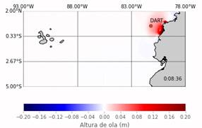
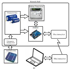
Under this scenario when a Tsunami occurs near to Ecuadorian shore and there is less than 10 minutes to evacuate, it is proposed that a Tsunami Early Warning System to automatically alert coastal cities, under severe risks, based on the reading from the Tsunami Buoys located at Ecuadorian waters, would improve the chances of saving lives. The proposed system has four components, a Buoy Station, Message Routing Station, Monitoring Station and Alert Station. The system architecture can be seen in Figure 2. The Buoy Station is self-powered and an hermetic device attached to a Tsunami Buoy with electrical and logical access to the measures of the BPR.
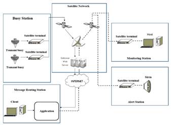
This device has a satellite terminal inside. The Alert Station is a device installed on a pole with a siren located near the shore of a coastal city. The Monitoring Station is a device installed in a Tsunami Warning Center, in this case at INOCAR facilities. These devices are communicated by a satellite network. Every device has a low consumption short-burst data satellite terminal. The access to the satellite network is trough the cloud. The Message Routing Station automatically access an associate account of the satellite terminals and routes the message among the stations. The Message Routing Station is a PC working in a client-server configuration. When a Tsunami event is detected, the Buoy Station sends a message to the Monitoring Station and Aler Station to automatically trigger the sirens without an operator.
Initially for this application it was considered a direct RF data link in the UHF band like described by Varney & Méndez, [15]. However the distance of the Tsunami buoys from the Ecuadorian shore, more than 50 nautical miles, could make this RF solution not suitable. Therefore, several satellite services providers were analyzed to implement the proposed architecture. The geographical location of the satellite terminals is near to the Equatorial line. It was taken into consideration satellite terminals connected to Iridium or Inmarsat network. Due to the geographical location of the devices from the proposed architecture and the geostationary Inmarsat satellite constellation, a satellite terminal that uses the Inmarsat network was selected.
Figure 2 shows the proposed Tsunami Early Warning System Architecture.
The selected satellite terminal was Skywave IDP 690 for marine applications and IDP 680 for land applications. These satellite terminals operated through the Inmarsat satellite network.
2.2. Buoy station
2.2.1. Tsunami buoys in Ecuador.
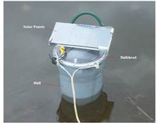
Ecuador has got two MESEMAR Tsunami Buoys DART II (Deep-ocean Assessment and Reporting of Tsunami) operated by INOCAR. These buoys are located near the Manta and Esmeraldas shores at the coordinates 1 7.8’S, 81 46’W and 0 38.47’N, 81 15.70’W [16]. A deployed buoy by INOCAR at Ecuadorian waters is shown in Figure 3 [17]. The Dart II System is formed by a Bottom Pressure Recorder (BPR) and a surface buoy. The BPR is located at the seafloor, communicated with the surface buoy by an acoustic data link. The surface buoy has a satellite terminal to send data frames to the Tsunami Warning Monitoring Station in approximately real time.
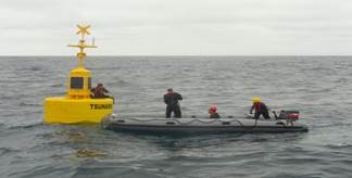
The buoy has an acoustic transceiver connected to the CPU that manages the onboard resources and communications. Internally the buoy has a compartment to store the onboard electronics and batteries from the harsh sea environment. The buoy is anchored by ballast at a fixed point. The buoy has an adequate separation between the center of mass and center ofbuoyancy to ensure stability in the water column. The diameter is 2.5 m and the displacement is near 4000 Kg. The buoy is self-powered for extended stay at sea, usually uses solar panels and batteries to store the energy. Currently, these buoys are communicated with the MESEMAR servers thought an Iridium satellite link. The data is accessed trough a web application. As a backup system INOCAR has got a satellite terminal BGAN Hughes to ensure access to the cloud in case of a catastrophic failure of networking infrastructure due a major earthquake. In case of a Tsunami event the information sent by the buoy is processed and analyzed manually, and then a Tsunami warning could be issued for the population that lives at coastal cities.
2.2.2. Proposed buoy station hardware.
The buoy station is a self-powered device with the appropriate size and mass to avoid significant displacement of the buoy’s center of mass. The buoy station has a cylindrical shape and can be installed externally, on the mast of the buoy. The hull of the buoy station is made by reinforced UV resistant plastic and has removable bulkheads to access the onboard electronics. The diameter is less than 30 cm and height less than 40 cm. The bulkhead has O-rings and penetrators for underwater environment to ensure hermeticity for the onboard electronics. The onboard electronic is formed by the satellite terminal Skywave IDP 690 and power supply. The proposed architecture can be seen at Figure 4.
The terminal Skywave IDP 690 delivers data over the IsatData Pro service using the global Inmarsat constellation [18]. The terminal is inside the buoy station to protect it from sea environment. The IDP 690 has an external RS232 port and four input/output analog or digital pins. The RS232 port can be connected to the CPU of the MESEMAR buoy to have access to the data frame of the BPR. The terminal has an internal microcontroller that manages the resources. This microcontroller is programming by scripts implemented by open source Lua programming language. Also, it is included a framework with the necessary tools for the developers. The firmware for this application will process the data frames from the Tsunami buoy CPU and generates messages to the alert station and monitoring station. The terminal can send messages up to 6400 bytes and receives message up to 10000 bytes. The typical latency is less than 30 s with messages of 100 bytes. The input voltage is between 9 to 32 V. An important characteristic is the “sleep mode” usefully to save energy. The consumed energy depends on directly of the message length and number of messages per day.
The buoy station power supply is composed by solar panels and an ultracapacitors stack. The usage of ultracapacitors allows high endurance without maintenance at sea. The size of the ultracapcitors and number is calculated from the necessary energy to transmit and receives a message and the number of message per day. Typically, the weather at Ecuadorian waters is cloudy as can be seen in Figure 3. For this reason, the number of solar panels is calculated to operate with low solar radiation level. This application requires more than the 2.7 V of a typical ultracapacitor, therefore the ultracapacitors are connected in series. An essential part of ensuring long operational life for this configuration is to balance each ultracapcitor to prevent current leakage from causing damage to other ultracapacitor through over-voltage.
The balancing circuit is a resistor connected in parallel with each ultracapacitor. The charging process is controlled by a charging circuit that uses low consumption operational amplifiers to implement a hysteresis loop. The ultracapacitors are charged to the upper threshold of the hysteresis, when this threshold is reached, a MOSFET transistor is activated turning on the IDP 690. An analog/digital input of the IDP 690 is used to monitor the voltage level of the ultracapacitor stack. The IDP 690 has the maximum energy consumption during the transmission with current peaks of 10 A and average current of 0.75 A. This characteristic of the satellite terminal is critical to estimate the required energy to operate during the night. The required energy stored in a capacitor is:
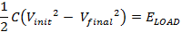
Where C is the total capacitance, Vinit is the voltage of the upper threshold of the hysteresis loop, Vfinal is the lower threshold of the hysteresis loop and ELOAD is the required energy for operation.

Using the electrical data from the IDP 690 datasheet the required energy to operate during the night was estimated. Assuming a maximum number of 40 messages of 200 bytes, the estimated required energy is 4027 J. With a safety factor of 2, the required energy is fixed on 10000 J, stored on 10 ultracapacitors of 400F/2.5 V with a hysteresis window of 10 to 25 V.
2.2.3. Proposed buoy station firmware.
The firmware implements the algorithms that manage the data frames from the Tsunami Buoy CPU. Initially the system goes to sleep mode where the current consumption is less than 100 uA. The sleep state is interrupted by the timer, low voltage level, incoming data frame on the RS232 port or if messages from the modem are received. The interruption flags are checking every 20 ms. A message called STATUS is send every six hours to the Monitoring Station, contains information about voltage level of the ultracapacitorsand other internal parameters of the IDP 690.
Also, the operator at the Monitoring station can request the delivery of a STATUS message from the buoy station.
In accordance with Meinig, Stalin, Nakamura, Milburn, [4], the DART II buoys have two reporting modes: standard mode and event mode. The event mode reportsevents like earthquake and/or tsunami when a threshold is exceeded. When an event data frame is received on the RS232 serial port, an encrypted message is sent autonomously to the Alert Station and Monitoring Station. The encryption is based on AES 256. The message to the Alert Station is sent until an acknowledge message is received. In case of a critical voltage level is reached, the satellite terminal goes to sleep mode until the voltage returns to a normal value.
2.3. Alert, Monitoring and Message Routing Stations
The Alert and Monitoring Stations have a similar architecture of the Buoy Station. The Alert Station is powered by solar panels; the energy is stored in an ultracapacitors stack. The Alert Station uses a satellite terminal IDP 680 for land applications. A difference between the IDP 690 and IDP 680 is the elevation angle. IDP 690 has a low elevation angle to operate at sea. The Alert Station is connected to local Tsunami Warning Sirens trough a Xbee transceiver. Figure 5 shows the Alert Station proposed architecture.
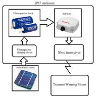
The Alert Station electronics are contained in an IP67 enclosure for outdoors environment and uses the same ultracapacitor stack for the Buoy Station. The firmware for the Alert Station has a similar behavior of the Buoy Station. Under the sleep mode the system gets to a wake up state by a timer, low voltage level or when a message is received from the modem. The received messages are two: EVENT and EXERCISE. The EVENT message is generated by the Buoy Station and triggers the Tsunami Warning Sirens then an acknowledge message is send to the Buoy Station. The EXERCISE message is generated by the Monitoring Station to test the Tsunami Warning Sirens.
The Monitoring Station is, basically, an IDP 680 satellite terminal connected via RS232 serial port to a PC, located at INOCAR facilities. As a backup energy system, the monitoring station has an ultracapacitor stack and solar panels. The firmware for this station works in transparent mode receiving and sending the message to the PC. The messages are managed by a Labview application running on a PC.
The messages from the IDP satellite terminals can be acceded through an application in the cloud provided by the IsatData Pro services. The message Routing Station is a PC where an application is already running to route automatically the message between the stations. The geographical location of the PC is near to a Gateway Earth Station that supports communications for the IDP terminals. Every satellite terminal has an assigned IP address, the client application uses these IP address to route the messages between the stations.
3. Results and discussion
A test stand was implemented to test this project. Using a 3D printer, a prototype of the Buoy Station was constructed. The cost of the prototype was less than USD 600. The satellite terminal is a low-cost Iridium Short Burst Data Transceiver 9602 with a transmit current (peak) of 2A. This transceiver has got an associated web account to send and receive messages from a PC. The transceiver is connected to an open source hardware platform Arduino UNO development board. Also, the development board is connected with a RF transceiver Xbee Pro.
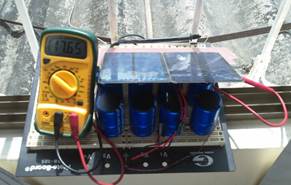
The development board is connected to an ultracapa-citor stack trough a 5V DC-DC converter. The ultracapacitor stack is composed by 10 Maxwell 450 F ultracapacitors with a passive balancing circuit. The hysteresis upper limit is 22 V the lower limit is 7.5 V. The system is powered by a set of 3 solar panels connected in series. Each solar panel can deliver 9V, 200 mA with mid-day sunlight. A PC is connected to the system through a Xbee RF data link. The Iridium Transceiver has got an associate web account to send and receives the messages. The components of the Test Stand are shown in Figure 6.
The charging circuit was tested in laboratory environment with the ultracapacitor stack to adjust the hysteresis window and verify the circuit protection to avoid damage to the ultracapacitors. The test is shown in Figure 7. The ultracapacitor stack takes less than 3 hours to get full charge.
The firmware stored in the Arduino development board emulates the behavior of the Buoy Station, Alert Station and Monitoring Station. Labview applications running on a PC process the message and data from the Iridium Transceiver and Xbee transceiver respectively. After the power supply was tested, the components were installed onboard the Buoy Station. The Buoy Station Prototype was deployed at a lake continuously for 30 days, sending and receiving messages through the satellite terminal and Xbee without energy storage problems.
For this test, the messages for the Iridium Transceiver have a length of 100 bytes. A magnetic switch activates the charging process of the ultracapacitors. When the voltage level was 21.8 V the Arduino and Iridium Transceiver turned on, after an initialization process a STATUS message was sent and the system goes to sleep mode, consuming 300 uA. Every six hours the system sends a STATUS message.
The PC can send commands via Xbee to simulate a Tsunami event, immediately an EVENT message was sent. After a delay, the EVENT message appears in the associated web account as a new message in the inbox. The minimum Iridium transceiver latency was 30 s, the maximum Iridium transceiver latency was 170 s.
The Xbee coverage was 1200 m with line of sight. The system also works as an Alert Station, when an EVENT or EXERCISE message was sent from the web account, the system sent a data frame to trigger a hypothetical Tsunami Siren trough the Xbee data link. The received data frame is visualized in a Labview application running on the PC. During the day an average rate of 2 message/hour were sent using the Iridium Transceiver. The average voltage level during the 30 days was 17.6 V. During the night, the achieved max number of messages was 87 before the voltage level dropped under the lower limit. After the sunrise, the system toke near 4 hours to get fully charge and start again.
In cloudy days with less than 2 hours of plenty sunlight, the voltage level dropped to 13.4 V. After 30 days, the Buoy Station was disassembled to inspect internal components. Firstly, they were inspected for sings of corrosion and leaking from the bulkhead, there was no evidence of corrosion or leaking. The voltage level of each ultracapacitor was measured to ensure correct operation of the passive balancing circuit. The ultracapacitors have an average voltage of 2.5 V. This was the unique field test. More testing will be carried out at sea. A disadvantage of the Buoy Station Prototype is the material, it is not tested against UV radiation from the sun. Large UV radiation exposure at sea probably could compromise the structural integrity of the device. The passive balancing circuit might not guarantee the ultracapacitor endurance greater than 5 years. It is considering an active balancing circuit with low power consumption.
4. Conclusions.
A Tsunami Early Warning System that can fully autonomously issue an alert to protect the population of coastal cities under the scenario of a local Tsunami event that could arrive in less than 10 minutes was presented. This paper proposed the design of Tsunami Early Warning System for coastal cities based on satellite terminals and ultracapacitors as a storage energy unit powered by a solar panel array to ensure long term deployments without maintenance. Based on the experiments carried out, the proposed project for an early warning Tsunami System turned out as appropriate.
Long-term test runs have to be done at sea environment to get more results of endurance, robustness and identify potential maintenance problems. Future works include the usage of IDP satellite terminals and stations installed on real work locations, at a Tsunami Buoy, a Coastal City and INOCAR installations. Also, more study is required to integrate the proposed buoy station to the MESEMAR Tsunami Buoy on the mechanical and electrical systems. The network architecture designed in this work can also be used for volcanic eruption, flood or industrial accident early warning systems.

