


 Inglés (pdf)
 Articulo en XML
 Referencias del artículo
 Enviar articulo por email
 Citado por SciELO
  Similares en
SciELO
Similares en
SciELO 
 Permalink
INTRODUCTION
Glass Fiber Reinforced Polymer (GFRP) decks are still considered novel applications in Civil Engineering. Nevertheless, these elements have been increasingly used in the rehabilitation and construction of road bridges due to several benefits such as: low maintenance cost, dead load reduction, electromagnetic transparency, fast installation, corrosion resistance, and high strength-to-weight ratio.
According to Mara et al. (2014), FRPs also offer sustainable solutions in bridge projects, reducing environmental impact and leading to potential cost savings over the life cycle of a structure. For instance, it has been estimated that carbon emissions could be reduced by 48 % if a GFRP is used instead of concrete for the superstructure of a 12 m long road bridge (Resins, 2009). A comprehensive review about the structural performance of FRP decks for road bridges can be found in Mara and Haghani (2015).
Among the different types of GFRP deck systems, pultruded panels are the most common since their manufacturing process is automated, allowing mass production of the elements and cost savings. As a result, several road bridges around the world have incorporated these panels (Lee et al., 2010; Joint Research Centre, 2016; Kim, 2019). The inherent lightweight nature of GFRP panels is a major advantage over conventional concrete or steel bridge decks, but it may lead to excessive vibrations induced by traffic loading (Aluri et al., 2005; Zhang et al., 2006). In addition, the structural response can be exacerbated by the road surface condition (Oliva et al., 2013) and the degree of composite action between the main girders and the deck (Wan et al., 2005). Therefore, the dynamic performance of a bridge with GFRP elements should be properly assessed considering these parameters. Modeling and analyzing the response of hybrid bridges that include pultruded decks may lead to computationally expensive problems due to two main factors. The first aspect is the complex geometry of the cross-section, which is generally a multicellular hollow profile. Whilst the second reason is that webs and flanges, also known as laminates, of the profiles may present different mechanical properties. Hence, this paper investigates the response of a hybrid GFRP-steel road bridge under the action of a vehicle when a multicellular deck system is modelled as an orthotropic plate with equivalent elastic properties. For this purpose, a Finite Element (FE) model of the bridge described by Keelor et al. (2004) is developed, and a sensitivity analysis is carried out to study the influence of the mechanical properties of the orthotropic element on the bridge behavior.
For the analyses, the H20-44 truck, described in AASHTO (2012), is modeled as a multibody dynamic model to account for the Vehicle-Bridge Interaction (VBI) phenomenon. Also, the irregularities of the pavement together with the degree of composite action between the GFRP plate and the steel stringers are considered.
After this introduction, the paper is organized as follows. In Section 2, the GFRP-steel bridge is described, and the equivalent elastic properties to model the multicellular deck as an orthotropic plate are introduced. The FE model of the road bridge and results from a static analysis are presented in Section 3. In Section 4, modeling the road surface, the multibody dynamic vehicle, and VBI are explained. A sensitivity analysis varying the properties of the orthotropic plate is carried out in Section 5. In Section 6, the bridge dynamic response is discussed in terms of the vehicle speed, the degree of composite action, and the road surface quality. Finally, conclusions are drafted in Section 7.
2. GFRP-STEEL ROAD BRIDGE
In this section, the GFRP-steel bridge is described. Also, expressions to obtain equivalent elastic properties to model a multicellular profile panel as an orthotropic plate are presented.
Description
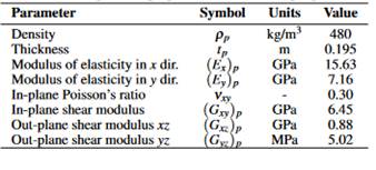
The Boyer Bridge, described by Keelor et al. (2004) and analyzed in this work, is a simply supported road bridge with a length Lb of 12.95 m and width of 7.92 m (Figure 1a). The clear span of the bridge is 12.65 m, and the superstructure consists of GFRP pultruded panels placed onto five galvanized steel stringers W610X155 Grade 345. These stringers are laterally restrained by C310x37 steel elements. The deck system, comprised of multicellular profile panels, is connected to the steel stringers by shear studs. Two studs are welded every 0.61 m along the length of the top flange of each stringer, and grout is poured along a haunch with a depth of 12.70 mm at the deck-girder interfaces. Finally, a 0.102 m layer of asphalt over the GFRP panels works as a wearing surface.
Orthotropic plate
Based on the proposal by Qiao et al. (2000), a multicellular deck system can be considered as an orthotropic plate with equivalent elastic properties using the following expressions:
where Dx and Dy are the bending stiffness of the cellular deck in x and y direction, respectively, Fx and Fy are the out-plane shear stiffness in x and y direction, Dxy is the torsional stiffness per unit width, tp is the thickness of the plate, bp is the width of the plate, lp is the length of the plate, νxy is the Poisson’s ratio, nc is the total number of cells, and b is the width of a single cell. Equations (1)-(6) are employed considering that the GFRP panels of the Boyer Bridge have the same geometry and mechanical properties of those used in the S655 Bridge. Information about the deck, whose cross-section is shown in Figure 1b, can be found in Wan et al. (2005). Additionally, for the calculation, bp = 12.95 m and lp = 7.92 m are adopted. Table 1 presents the equivalent properties of the orthotropic plate.
3. NUMERICAL MODELING
In this section, the FE model of the road bridge is firstly described. Secondly, experimental and numerical results from a static test are compared. A modal analysis using the numerical model is thirdly carried out to determine the modes of vibration of the structure.
Finite Element model
A FE model of the Boyer Bridge is developed in ABAQUS (SIMULIA, 2020), as shown in Figure 1c. Node reduced integration shell elements (S4R) are considered for modelling the orthotropic plate, girders, and cross-beams. The material for the stringers and cross-beams is assumed isotropic with the following values: ρ s = 7750 kg/m3, E s = 200 GPa and ν s = 0.32. Whilst the properties of the material for the GFRP plate are stated in Table 1.
The grout haunch is not modeled, but a gap of 12.70 mm is provided between the bottom part of the deck and top flanges of the beams to represent the real geometry of the bridge. Additionally, a non-structural mass of 225 kg/m2 is assigned over the deck to account for the asphalt layer. To model a full composite action, tie constraints are employed between the top flanges of the beams and the corresponding bottom surfaces of the deck. This aims to reproduce a total transfer of the horizontal shear loads between the deck and stringers.
For the boundary conditions, displacements of the bottom flanges of the stringers are constrained in the longitudinal, transversal and vertical (x, y and z) directions at one end of the structure. Whilst, transversal (x) and vertical (z) displacements of the bottom flanges at the another end are constrained.
Static test
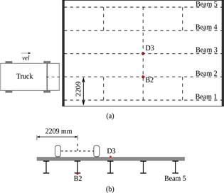
Employing the FE model, the static behavior of the bridge is assessed under the action of a three axle truck. The results obtained from this numerical model are contrasted with the experimental measurements reported by Keelor et al. (2004). The test setup is displayed in Figure 1d, where just the two rear axles appear since the first axle was off the structure during the test. The weights of the axles are 46.37 kN (P3), 41.92 kN (P4), 46.60 kN (P5), and 40.57 kN (P6), and each one acts on a surface of 0.25 m x 0.51 m (Jiang et al., 2013). In Figures 1d-2a, the strain gauges located at the flanges of each beam at 0.305 m from midspan are shown. The strains obtained for the Beam 2 are presented in Figure 2b, where the neutral axis positions measured from the bottom flange are 415 mm and 427 mm considering the experimental and numerical results, respectively.
Comparing the curvature κ in each stringer, the difference between the experimental and numerical values for Beams 1, 2, 3 and 4 are -3 %, +9 %, +18 %, and -17 %, respectively. Since data for the Beam 5 was no collected during the test, no comparison is drawn in this element. Based on the obtained results, it is assumed that the developed FE model predicts accurately enough the bridge performance.
Modal analysis
The dynamic response of a bridge under traffic loads can be anticipated by a simple inspection of its vibration modes, so a modal analysis is performed. Figure 2c presents the first three numerical vibration modes of the GFRP-steel bridge.
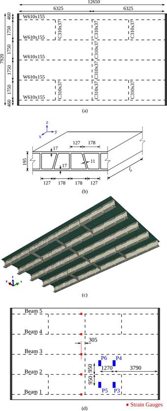
Figure 1 Boyer Bridge: (a) Plan view, (b) GFRP bridge deck, (c) FE model, and (d) Static test. Units in mm
Mode 1 is a vertical bending mode at 8.87 Hz, Mode 2 is a torsional mode at 11.06 Hz, and Mode 3 is a transverse flexural mode at 20.02 Hz.
Since partial composite action between the deck and the stringers is later studied in this paper, an analysis accounting for this feature is carried out. Rigid connectors are employed instead of the tie constraints mentioned in Section 3.1. Elements type CONN3D2, every 0.61 m, are used to connect nodes of the beams top flanges and the corresponding nodes of the deck in the longitudinal (y) and vertical (z) directions. No constraints are modeled in the lateral (x) direction to represent the reduction in the transfer of the horizontal shear load. The mode shapes are similar to those shown in Figure 2c, but the natural frequencies decrease. The fundamental frequency is 8.36 Hz, whereas values of 10.39 Hz and 18.15 Hz are computed for Modes 2 and 3, respectively.
4. VEHICLE-BRIDGE INTERACTION
This section presents the generation of roughness profiles to describe the road surface. In addition, the multibody dynamic model of the vehicle is introduced, and the modeling of VBI is explained.
Road surface
Road roughness is an important source of dynamic excitation in VBI problems, so a proper definition of the pavement irregularities is key for the analysis. In general, road roughness can be represented by an ergodic stationary Gaussian random process described by its Power Spectral Density (PSD). ISO (2016) proposes the expression G(n i ) = G(n 0)(n/0.1) −2 for a one-sided PSD, where n is the spatial frequency in cycle/m, and G(n 0) is the spectral roughness coefficient that depends on the road quality in m3/cycle.
A hypothesis of road surface isotropy and homogeneity is assumed in this paper, so parallel profiles of irregularities along the road share statistical properties but they are not the same. Based on Sayers (1988), the profiles for left and right tires can be obtained through the following expressions:
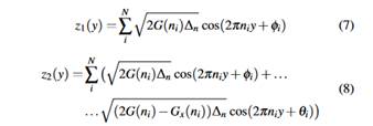
where N is the number of discrete frequencies ni in range [0.01, 10], ∆n is the increment between successive frequencies, Gx(ni) is the cross-PSD, and φi and θi are random phase angles from 0 to 2π.
Vehicle
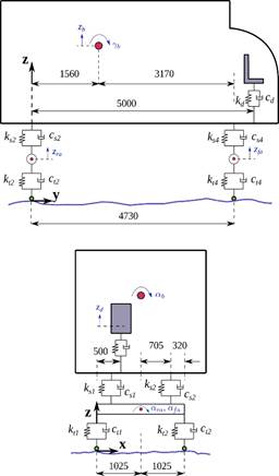
A H20-44 truck described in AASHTO (2012) is employed in this study. Eight DOFs are assigned to the whole multibody dynamic model, as displayed in Figure 3. The vehicle consists of individual rigid bodies that represent the box and axles, plus a mass point that reproduces the driver seat. The rigid bodies are connected by linear springs and dashpots to consider the mechanical properties of the suspensions and the behavior of the tires.
The box has 3 DOFs, vertical displacement (zb), pitch (γb), and roll (αb). Each axle is provided with 2 DOFs, vertical displacement (zra and z f a), and roll (αra and α f a). Finally, the driver seat has 1 DOF, vertical displacement (zd ). Considering Marchesiello et al. (1999), the main properties of the vehicle are: mb = 17000 kg, m ra = 1000 kg, m f a = 600 kg, k t1 = k t2 = 1.57 × 10⁶ N/m, kt3 = kt4 = 7.85 × 10⁵ N/m, ks1 = ks2 = 3.73×10⁵ N/m, ks3 = ks4 = 1.16×10⁵ N/m, ct1 = ct2 = 200 N s/m, ct3 = ct4 = 100 N s/m, cs1 = cs2 = 3.50 × 10⁴ N s/m, cs3 = cs4 = 2.50 × 10⁴ N s/m, Iαra = 600 kg m2, Iα f a = 550 kg m2, Iαb = 1.30 × 10⁴ kg m2, and Iγb = 9.00 × 10⁴ kg m2. For the driver seat, md = 85 kg is assumed, whereas the values for the spring (kd = 10.51 kN/m) and the dashpot (cd = 876 Ns/m) are based on Zuo and Nayfeh (2007).
Interaction
VBI is achieved by means of contact between the bottom nodes of tire elements and the deck surface. This analysis is performed in ABAQUS (SIMULIA, 2020), which provides capabilities to model the vehicle through a multibody system and the structure through finite elements. The vehicle, the bridge, and the interaction phenomenon lead to a nonlinear coupled system, whose global system of equations may be expressed as follows:
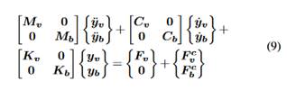
where Mv, Cv and Kv are the mass, damping and stiffness matrices of the vehicle, Mb, Cb and Kb are the mass, damping and stiffness matrices of the bridge, Fv is the external force vector of the vehicle due to its self-weight, F c v is the force vector applied on the vehicle as consequence of the interaction with the bridge, F b c represents its counterpart on the structure, yv and yb are the acceleration response vectors, yv and yb are the velocity response vectors, and yv and yb are the displacement response vectors of the vehicle and bridge, respectively.
5. SENSITIVITY ANALYSIS
A sensitivity analysis is presented in this section to identify the most relevant mechanical properties of the orthotopic plate on the numerical response of the GFRP-steel structure. Additionally, the response of the hybrid road bridge is assessed when some properties of the deck are modified.
Identification of relevant properties
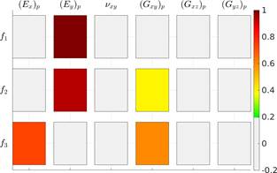
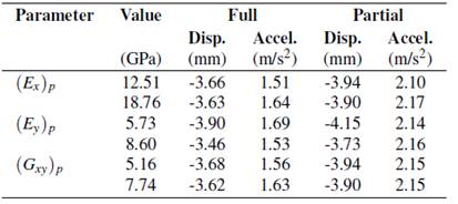
Focusing on the natural frequencies of the hybrid bridge, a global sensitivity analysis aiming to identify the most relevant material properties of the orthotropic plate is performed herein. The properties of the plate ((E x ) p , (E y ) p , ν xy , (G xy ) p , (G xz ) p and (G yz ) p ) are assumed to be described by a two-parameter Weibull probability distribution based on Alqam et al. (2002). Mean values for the distribution of each property are taken from Table 1, and a coefficient of variation of 10 % is considered. Also, the Latin Hypercube Method is used to generate 500 multivariate stochastic samples of the mechanical properties. Parameters related to boundary conditions, steel elements and density of the materials are not considered in this analysis.
Figure 4 shows the results through the Spearman correlation coefficient matrix, where values between [−0.2, +0.2] are excluded for a better visualization. From the correlation matrix, it is seen that the longitudinal modulus (E y ) p , the transverse modulus (E x ) p , and the shear modulus (G xy ) p of the deck are the most influential factors to obtain the natural frequencies of the FE model of the bridge.
Variation of relevant parameters
Based on the previously obtained results, a parametric study varying (E y ) p , (E x ) p , and (G xy ) p is carried out hereby. The mean value of each property (Table 1) is modified 10 % in a range from 80 % to 120 %. For the analyses, the H20-44 truck is aligned with the center line of Beam 2 (Figure 5a), and a velocity of 60 km/h is considered.
The displacement response at the midspan bottom of Beam 2 (point B2) is calculated, and the acceleration response at the deck center (point D3) is obtained. In Figure 5b, the points where the structural response is computed are shown. A very good quality surface of the pavement (Class A according to ISO (2016)) is considered for the simulations.
For the sake of statistical significance, ten synthetic pairs of profiles, whose irregularities are sampled every 2 cm, are generated. Equations (7)-(8) are used for the definition of the road roughness, adopting G(n o ) = 16× 10 −6 and 2000 spatial frequencies between 0.01 m −1 and 10 m −1 . To obtain G x (n i ), the procedure described by Oliva et al. (2013) is employed. To ensure that the truck presents a stable response due to the pavement irregularities before entering the bridge, the vehicle is considered to start traveling with its rear tires located at -50 m of the longitudinal model coordinate (y = 0 corresponds to bridge entrance). The calculation is also performed until the rear tires are 35 m after the exit abutment. Hence, the vehicle runs a distance equal to 50+L b +35 m.
Since the implications full and partial composite actions between the deck and the stringers are also studied, 300 dynamic analyses are carried out in total. To solve the system of differential equations (Equation (9)), the HHT-α implicit integration method is used, a constant time step of 0.001 s is set, and a Rayleigh damping of 1 % is adopted.
In Figure 6, the computed results are presented. The graphs show the average of the peak responses (mean of absolute maximum values), displacement at point B2 and acceleration at point D3, when the parameters of the orthotropic plate change. The colored bands in the plots represent the peak responses obtained after using the ten set of road roughness profiles. As expected, higher displacements and vibration levels are obtained for the partially composite model of the bridge in comparison with the fully composite one. Table 2 presents the dynamic responses for both models of the GFRP-steel bridge. These results are the average of the ten peak responses obtained when the value of the analyzed property is multiplied by 0.8 and 1.2, respectively.
By varying ±20 % the relevant properties of the orthotropic plate
in the fully composite model, the average of the peak responses
changes up to:
Displacement: 1 %, 12 %, and 1 % for the variation of (Ex)p, (Ey)p, and (Gxy)p, respectively.
Acceleration: 2 %, 6 %, and 2 % for the variation of (E x ) p , (E y ) p , and (G xy ) p , respectively.
Whilst in the partially composite bridge, modifying ±20 % the equivalent properties of the deck system lead to the following variations of the average the peak responses:
Displacement: 1 %, 11 % and 1 % for the variation of (E x ) p , (E y ) p and (G xy ) p , respectively.
Acceleration: 2 %, 6 % and 2 % for the variation of (E x ) p , (E y ) p and (G xy ) p , respectively.
6. DYNAMIC RESPONSE
In this section, the Dynamic Amplification Factor (DAF) of the GFRP-steel bridge is discussed varying the truck speed and the quality of the road surface. Also, the acceleration response of the driver seat in the vehicle is presented.
For the numerical analyses, the considerations mentioned in the previous section are adopted. Also, the H20-44 truck is assumed to move at 40, 60, 80 and 100 km/h, and two road surfaces are defined. Hence, values of G(n o ) equal to 16 × 10 −6 (road A, very good quality) and 256 × 10 −6 (road C, regular quality) are employed. As ten pair of profiles are again generated for statistical significance, 160 simulations are carried out.
Dynamic amplification factor
The results at the bottom flange of the Beam 2 (point B2 in Figure 5) when the vehicle runs over the bridge at 100 km/h are presented in Figures 7a-b. The colored bands shown in these graphs represent the dispersion of response displacements obtained from the ten set of roughness profiles. The width of this band corresponds to the minimum and maximum displacements calculated. In the plots, results for a perfectly flat surface are also represented together with the maximum static displacement. It is clear that the response increases by worsening the quality of the road surfaced. Similarly, the reduction of composite action in the hybrid road bridge impacts negatively in the structural response.
Considering that the DAF is defined as:
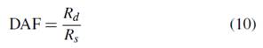
where Rd and Rs are the maximum dynamic and static responses of the bridge at a specific location, Figure 7c presents the maximum DAF at point B2 for different truck speeds.
Maximum results among the ten set of profiles, depending on the road class and composite action of the bridge, are shown. The DAF for a perfectly flat surface is also represented. Generally, in the graph, the higher the vehicle speed, the higher the maximum DAF. As expected, a higher bridge response is also obtained when the composite action is reduced, and the worse results are obtained when the partially composite model is assessed considering a poor quality of the road surface.
Driver seat
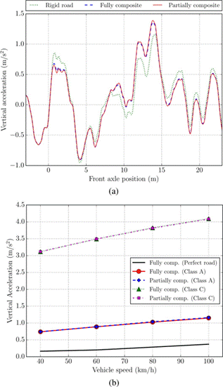
The vertical accelerations at the seat of the truck are analyzed herein to study the dynamic effects on the driver. Figure 8a shows the computed response for one set of road Class A synthetic profiles when the vehicle runs at 100 km/h. To assess the bridge flexibility influence, results of the truck on the bridge and on a rigid road platform are compared under the same road surface conditions. From this plot, it can be firstly seen that the degree of composite action in the model is not relevant on the driver comfort since similar accelerations are obtained. Additionally, the structure flexibility slightly modifies the response at the driver seat but it is not a key factor given the short span of the bridge.
In Figure 8b, the average of the peak vertical acceleration at the driver seat for different vehicle speeds is displayed. In this graph, acceleration when the truck runs over a pavement without irregularities (perfect road) is also included. It is clear that the road quality and the vehicle speed impact largely the peak response at the driver seat.
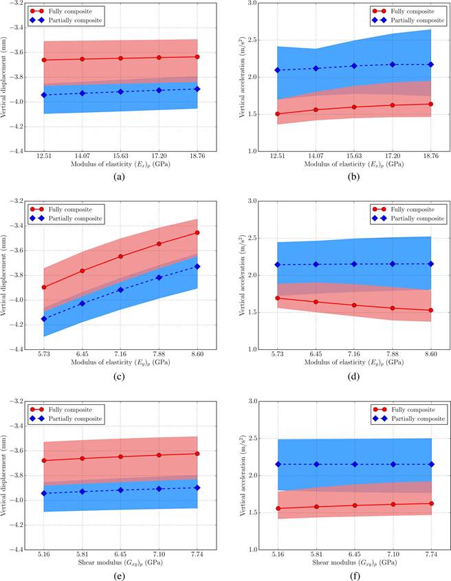
Figure 6 Truck running at 60 km/h in a road Class A: (a) Displacement at B2 varying (E x ) p , (b) Acceleration at D3 varying (E x ) p , (c) Displacement at B2 varying (E y ) p , (d) Acceleration at D3 varying (E y ) p , (e) Displacements at B2 varying (G xy ) p , and (f) Acceleration at D3 varying (G xy ) p
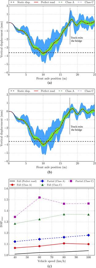
Figure 7 Vertical displacement of point B2: (a) Fully composite model when the vehicle speed is 100 km/h, (b) Partially composite model when the truck velocity is 100 km/h, and (c) Maximum DAF for different vehicle speeds
7. CONCLUSIONS
In this study, the dynamic behavior of a GFRP-steel road bridge has been assessed by carrying out an analysis considering VBI. The influence of the properties of a multicellular GFRP deck, modeled as an orthotropic plate, on the bridge response has been investigated considering the degree of composite action between the deck and the girders, the road roughness, and a multibody dynamic model for the vehicle. Based on the obtained results, the following conclusions may be drawn:
The longitudinal modulus of elasticity (E y ) p , transverse modulus of elasticity (E x ) p , and the shear modulus (G xy ) p are the most influential properties of the orthotropic plate on the dynamic performance of the hybrid road bridge.
Modifying ±20 % the mean values of (E y ) p , (E x ) p , and (G xy ) p does not lead to significant differences in the final computed response of the GFRP-steel bridge.
Numerical results confirmed previous observations about the importance of achieving full composite action between the girders and deck to control high dynamic responses in hybrid bridges.
In terms of the DAF, deterioration of road surface is more important than reduction of composite action. Hence, a good construction and a proper maintenance are of great importance for this kind of road bridge due to its dynamic sensitivity.
Road roughness is more relevant than the degree of composite action in regard to dynamic effects on the driver.