


 Espanhol (pdf)
 Artigo em XML
 Referências do artigo
 Enviar este artigo por email
 Citado por SciELO
  Similares em
SciELO
Similares em
SciELO 
 Permalink
1. Introduction
DC/DC converters have been used in many industrial applications which in general perform single quadrant operation. Traditional models like buck, boost and buck-boost converters (Pasha, Jayakumar, & Thiruvonasundari, 2017)have some applications oriented, mostly, to electrical power generations, photovoltaic and renewable energy sources (Chilambarasan, Ramesh, & Sujatha, 2014)(Saradha, Mrudhulaa, Priyadharshini, Seyezhai, & Mrdula, 2018) (Prasanna, Kirubakaran, Rahulkumar, & Rudhran, 2015) (Elavarasu & Christober, 2018), power regulation (Jayachandran, Krishnaxwamy, Anbazhagan, & Dhandapanl, 2015) and energy storage systems (Manikandan & Vadivel, 2013) (Sanjeevikumar amp; Rajambal, 2008).
However, the development of circuits capable of operating in four quadrants has become a necessity, especially in applications with smart grids, where it is necessary to control the charge and discharge of batteries or in the case of electric vehicles, where it is necessary to control the direction of the rotor axis in acceleration or braking state of a DC motor.
Luo-converters are an example of DC-DC power conversion circuits developed to perform positive to positive DC-DC voltage increasing conversion with high efficiency and near-zero output voltage and current ripples (Luo F. L., 1997).
The proposed LUO circuit depends on two semiconductors used as switches which are driven by a type of PWM signals with constant switching frequency controlled independently. A 4-pole double state switch (4PDS) is used for changing from forward and reverse states.
Each mode is controlled by one switch. Each state determines the output current path (Sujatha, Chilambarasan, & Ramesh, 2015), and to determine the direction of the rotor axis in acceleration or braking state. Multiple motor characteristics have been considered in the simulation tests, in order that the future implementation will be more reliable.
Free quadrant change is available, but it necessary to consider events like overcurrent in the entrance circuit loop and polarity change in the capacitor. Thus, it is important to determine safe conduction duty ranges to ensure system stability and integrity of the circuit elements, all depends on the characteristics of the loads. In this project, test results are presented for a DC motor load.
The difference between this work and the original proposed by Luo and Hong Ye in (Luo & Ye, Chapter 7 - Multiple quadrant operating Luo-Converters, 2003) is that it presents simulation results for the combined theoretical circuit named by them as “Circuit 3” with a little correction discussed in the next section.
2. COMBINED LUO-CONVERTER MODEL
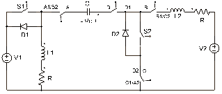
This section describes the combined circuit proposed by Luo and Hong Ye in (Luo & Ye, Chapter 7 - Multiple quadrant operating Luo-Converters, 2003) for four quadrant operation with a small variation, instead from using a three-pole double state switch (3PDS) for the commutation, as proposed in (Luo & Ye, Chapter 7 - Multiple quadrant operating Luo-Converters, 2003) (Luo, Ye, & Rashid, Four quadrant operating Luo-Converters, 2000), to a four-pole double state switch (4PDS) will be used as shown in Figure 1 otherwise, the proper circuit configurations will not be achieved.
The 4PDS switch defines 4 poles (A, B, C & D) and two states for each pole, it means that each pole has a common pin named A, B, C or D and each one of them has two pins, one for a first state (A1, B1, C1 or D1) and another one for a second state (A2, B2, C2 or D2).
V1 is the input voltage source, S1 and S2 are switches that control acceleration and braking modes, D1 and D2 are diodes, L1 is the entrance loop inductance, R is a resistance, C is a capacitor, V2 is the voltage load which represents the Electromotive Force (EMF) of a DC motor or the voltage value of a Battery in the case of a battery charge application, IL1 and IL2 are the currents which flow through inductors L1 and L2 respectively,
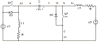
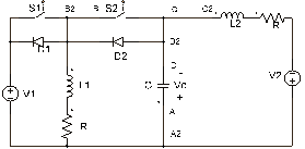
Figure 2 and Figure 3 show how the 4PDS works to switch from circuit 1 to circuit 2 in order to reach the Luo-converter circuit topology for operation in Quadrants I, II and III, IV respectively.
The circuit can work in four modes or quadrants as follows:
Lista Númerica
Mode A (Quadrant I): Forward acceleration.
Mode B (Quadrant II): Brake in forward operation.
Mode C (Quadrant III): Reverse acceleration.
Mode D (Quadrant IV): Brake in reverse operation.
For a comprehensive review of the functionality of these circuits, as explained by Luo and Hong Ye, refer to (Luo & Ye, Chapter 7 - Multiple quadrant operating Luo-Converters, 2003) (Luo, Ye, & Rashid, Four quadrant operating Luo-Converters, 2000).
Table 1 shows the operation mode of the circuit depending on the 4PDS and the states of switches S1 and S2.
The considered parameters for the circuit based on calculations in (Luo & Ye, Chapter 7 - Multiple quadrant operating Luo-Converters, 2003) (Luo, Ye, & Rashid, Four quadrant operating Luo-Converters, 2000) are:
Table 1. Modes of operation
|
Mode |
S1 |
S2 |
4PDS |
|
A (Quadrant I) |
PWM switching |
Off |
Pin A connected to pin A1 Pin B connected to pin B1 Pin C connected to pin C1 Pin D connected to pin D1 |
|
B (Quadrant II) |
Off |
PWM switching |
Pin A connected to pin A1 Pin B connected to pin B1 Pin C connected to pin C1 Pin D connected to pin D1 |
|
C (Quadrant III) |
PWM switching |
Off |
Pin A connected to pin A2 Pin B connected to pin B2 Pin C connected to pin C2 Pin D connected to pin D2 |
|
D (Quadrant IV) |
Off |
PWM switching |
Pin A connected to pin A2 Pin B connected to pin B2 Pin C connected to pin C2 Pin D connected to pin D2 |
3. SIMULATION RESULTS
3.1 Current behaviour for a
If V2 is positive and current IL2 is increased positively, it means that the circuit is trying to get the acceleration state. Furthermore, if V2 is positive and the current IL2 is increased negatively, then it determines a positive braking mode.
For negative acceleration state, V2 is negative and also the current IL2 is increased negatively and negative braking state is determined by a negative V2 with positively increasing of IL2.
3.2 Current behaviour for a DC motor load.
As shown in Figure 4, a DC motor is implemented as a load in the output where Ve represents the separately excitation voltage for the motor. Table 2 shows the motor parameters considered in the implementation.
Where, Ra is the Armature resistance, La is the Armature inductance, Rf is the field resistance, Lf is the field inductance, Vt is the Nominal voltage, Ia is the nominal current, n is the nominal speed.
Figure 5 shows the motor speed and the current in the output IL2 in acceleration and braking modes with a DC motor load. In purple it is shown the motor speed that defines positive acceleration in Figure 5a, brakes positively as shown in Figure 5b, accelerates negatively as shown in Figure 5c and brakes negatively as shown in Figure 5d. Braking is started in t=0.4 because it depends on acceleration state.
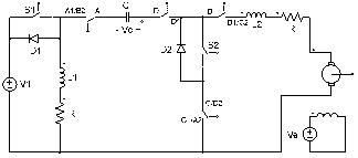
Table 2. DC Motor Parameters
|
Ra |
0,7 [Ω] |
|
La |
10 [mH] |
|
Rf |
75 [Ω] |
|
Lf |
20 [mH] |
|
Moment Inertia |
0,7 [kgm2] |
|
Vt |
120 [V] |
|
Ia |
10 [A] |
|
n |
500 [rpm] |
|
If |
1,6 [A] |
|
Ve |
120 [V] |
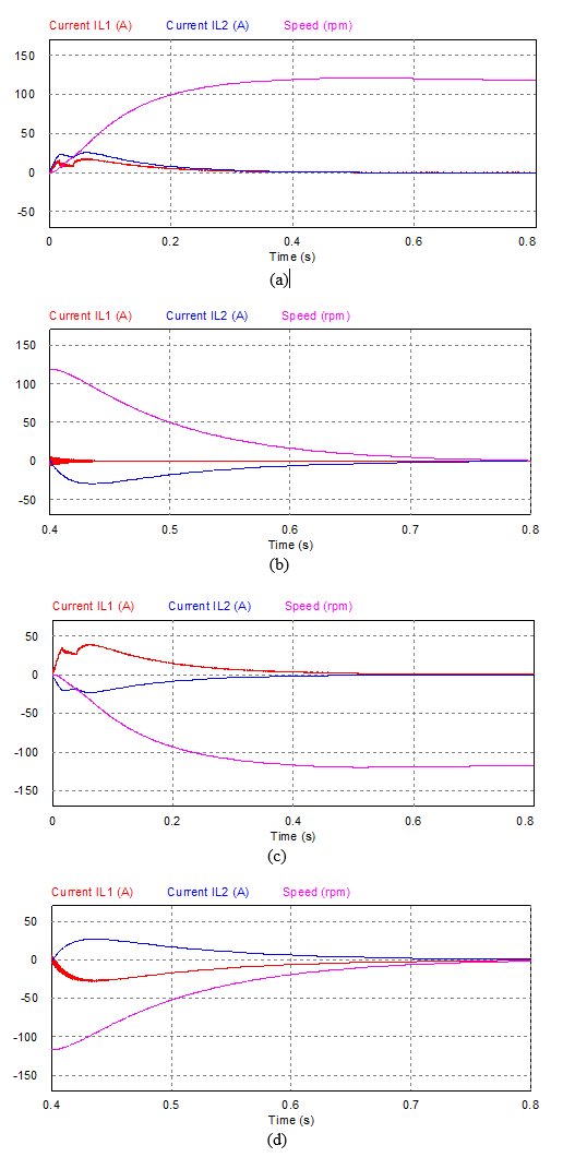
Figure 5 Speed output for a (a) motor load with
Duty cycle values were tested in the experimentation in order to obtain safe operation ranges. It was necessary because overcurrent values could damage the circuit and small values can make the circuit to respond extremely slow, then, the safe duty cycle range was between,
4. CONCLUSIONS
The proposed combined circuit model for a four-quadrant operation Luo-converter seems to be reliable for controlling a DC motor load in acceleration and braking modes. This is possible due to EMF, as a generating part of the output current increase positively or negatively depending on the operation mode.
The considered parameters for a DC motor make the circuit more reliable for a future implementation considering safe duty cycle ranges in order to protect the circuit integrity and stability. These ranges are,
It is important to consider maximum current values when suddenly changing quadrants, as these could damage circuit elements, e.g. a change from I quadrant to III quadrant over increases the input loop current.