


 Inglés (pdf)
 Articulo en XML
 Referencias del artículo
 Enviar articulo por email
 Citado por SciELO
  Similares en
SciELO
Similares en
SciELO 
 Permalink
1. INTRODUCTION
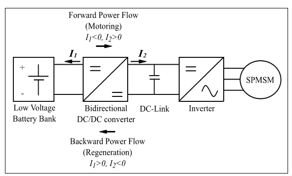
The use of an effective bidirectional power converter combined with modern energy storage systems and efficient electrical machines is a crucial aspect for the development of reliable electrically-powered traction applications. For these systems, to manage a double-way power flow, the use of a simple and robust DC-DC power converter plus an inverter is required. The converter that fulfills these features is a bidirectional non-isolated buck-boost type (Pillay et al, 1985) (Du et al, 2010) in one hand. And on the other hand, for the inverter, a three-leg three-phase topology having antiparallel diodes on each power switch has been considered. Therefore, these two power converters need to be effectively controlled to properly deliver energy from the battery to the electric machine when acting as a motor, and in the opposite case allowing to charge the battery by energy regeneration.
Depending on the speed-torque demand and profile of the electrical vehicle, the inverter has to supply the required voltage to the electric machine from the power converter.
In this study, due to its low inertia, high power density, controllability and outstanding efficiency; a Surface Permanent-Magnet Synchronous Machine (SPMSM) is used (Kitajima et al, 2014)(Maekawa et al, 2014). Consequently, to take advantage of these features and design a robust control scheme against load variations during motoring as well as regeneration modes, the development of a reliable and practical control strategy for the bidirectional DC-DC converter and also for the inverter is required; this is precisely the scope of this paper. This aim will be accomplished by the use of a nested control structure for the buck-boost bidirectional DC-DC converter and a vector control strategy for the SPMSM. The entire control logic was firstly validated by simulation and also via its digital upgrading in a commercial embedded system.
2. THE BUCK-BOOST BIDIRECTIONAL DC-DC CONVERTER
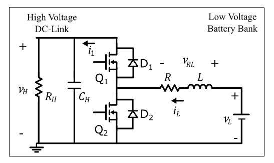
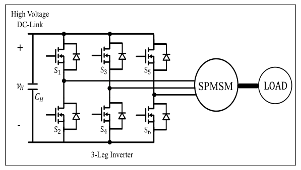
The overall components for electric vehicle applications are exposed in Figure 1 where the bidirectional power flows can be observed. This bidirectional power exchange is achieved by means of the bidirectional DC-DC power converter, whose topology is a buck-boost type, as it is shown in Figure 2. VL represents the battery voltage, VH the DC-link voltage, L and R denote the inductance and the internal resistance of the inductance respectively, RH the inverter input impedance, and CH is the DC-link capacitance. The two operation modes present opposite inductance current direction to achieve extraction or injection of energy from or to the low-voltage battery bank.
In this study, the unified current controller proposed by (Junhong et al, 2008) has been considered as the buck and boost modes have the same power plant. This approach relays on the opposite switching between switches Q1 and Q2. For the case of electric tractions applications, the major challenge for the DC-DC converter consists on regulating the highvoltage DC link provided that the low-voltage battery bank is a robust DC source that presents a relative slow discharge during normal operation. The ON and OFF states for the boost mode are shown in Figure 3.
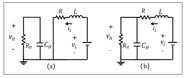
Thus, the state-space equations for the ON and OFF states are described by (1)-(2):
The average value of the previous equations can be expressed as (3)-(4):
where D represents the duty cycle of the pulse width modulation (PWM) on the power semiconductor. Finally, the state-space average equations (Erickson and Maksimovi, 2001) can be derived as detailed in (5):
As the DC-link voltage is controlled by means of the duty cycle, the understanding of the relationship between this variable and the other variables in steady state (
From the first line in Equation 7, (8) is obtained:
After simple mathematical treatment the duty cycle exhibited in (9) can be attained:
Where VRL denote the overall voltage on the inductor (across its inductance and internal resistance). As the duty cycle D is simultaneously related with the two state-variables ( IL and VH), the system places in a non-minimum phase condition (Tarakanath et al, 2014) which involves control instabilities. Hence, a cascade control scheme (See Figure 4) with an outer voltage loop and an inner current loop is used as the inductor current presents a higher frequency bandwidth than the DClink voltage frequency bandwidth.
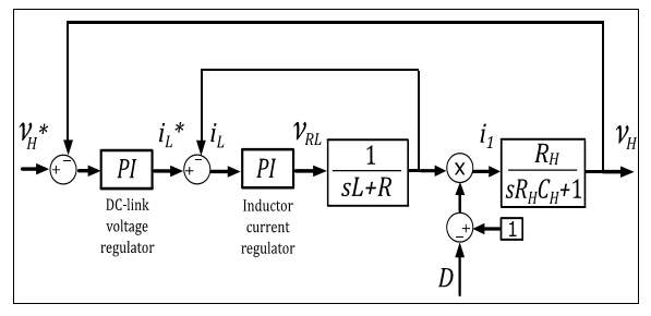
For both, the outer and inner control loops, PI regulators are proposed. From Equations 10-13, the proportional (Kp) and integral-terms (Ti) for the outer voltage controller and the inner current controller have been designed to have a closedloop bandwidth (BW) of 30[Hz] and 500[Hz] respectively. Using the pole-cancellation criterion, the controllers parameters can be estimated (Savaresi et al, 2010) by means of (10) (11) (12)-(13):
For the converter, R=0.5[Ω], C=2000[µF], L=25[mH] and VL=202[V] have been considered.
3. VECTOR CONTROL FOR THE SPMSM
Once the operation of the bidirectional converter has been discussed, the operation and control of the inverter and the traction machine are required. A three-phase two level inverter feeds the SPMSM (Figura 5).
Additionally, an external mechanical load directly coupled to the axis of the machine is used to operate in motoring and regeneration modes. The parameters of the SPMSM are shown in Table 1 at the Appendix section.
To design a successful control strategy, a rotating reference frame has been considered in order to operate and control in a rotating dq-coordinate system. In this dq-reference frame, the torque equation for a Permanent Magnet Synchronous Machine (PMSM) is given (Dominguez, 2015) by (14):
Where id and iq are the direct and quadrature currents respectively. As in a SPMSM Ld and Lq have the same value (Skvarenina, 2002), Equation 14 can be rewritten as in (15):
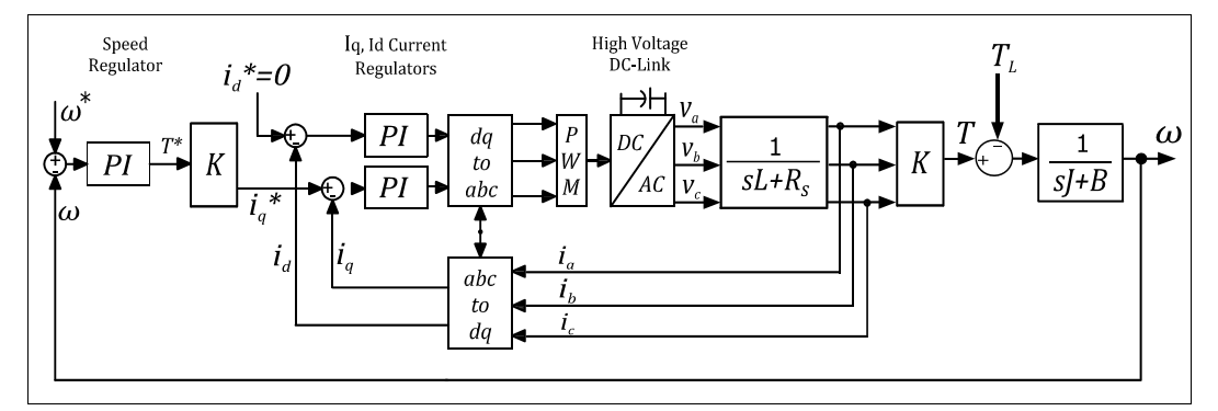
For electric traction applications, an outer superimposed speed controller is required where its output control signal is the torque reference for the inner current controller. To achieve this goal, a cascade control scheme is used as shown in Figure 6.
The inner control loop regulates the machine dq currents and the outer control loop regulates the machine angular speed w provided that the mechanical time constant of the machine is much greater than the electrical time constant. As the torque reference can be obtained from the superimposed PI speed regulator (Drury, 2001), the required quadrature current reference (iq *) can then be found from Equation 15. On the other hand, the direct current reference (id *) is set to be zero as the machine is a SPMSM. For the dq-current controllers, the selected closed-loop bandwidth (BWd,q) was 500[Hz]. To obtain the PI parameters, Equations (16)-(17) were used.
The methodology used to attain the PI parameters for the speed regulator is exposed in detail below. A similar procedure can be extended to the previously exposed controllers.
The torque-speed equation of the machine is as in (18):
Being J, B and the TL inertia of the shaft of the machine, the friction coefficient and the load torque respectively. Using the Laplace transform, the machine torque-speed transfer function P(s) can be written as (19) details:
On the other hand, the transfer function of the PI controller for the speed regulator can be written as in (20):
Comparing Equations (19) and (20) and employing again the pole-cancellation principle for the design of the controller, Tiw is chosen according to (21):
Therefore, the closed-loop transfer function L(s) of the system is exposed in (22):
The previous expression can be related with a first order low-pass filter having a cut-off angular frequency Wc exhibited in (23):
Being BWw the closed-loop bandwidth for the speed controller which was chosen to be 100[Hz]. Considering Equations (21) to (23), Kpw can now be obtained as in (24):
4. DIGITAL IMPLEMENTATION
The digital PI controllers were implemented using the Tustin numerical integration exposed in (25):
Where q0 and q1 relate to (26) and (27) respectively
Being, Uk and Ek the actual variable value and its actual error, while Uk-1 and Ek-1 refer to the previous Uk value and error respectively. In addition, Tc stand for the sampling time and Kp and Ti for the PI parameters correspondingly. Regarding the simulation, PSIM® Software was used to setup the overall system: the bidirectional DC-DC power converter, the inverter, the SPMSM and the programmable mechanical load. After successful results were attained, all the control logic was digitally upgraded in the simulator for a Texas F28335 DSP using the SimCoder® add-on which generates all the C-code required to be directly programmed on the DSP to work properly. This option considerably reduces the prototyping process.
5. EXPERIMENTAL RESULTS
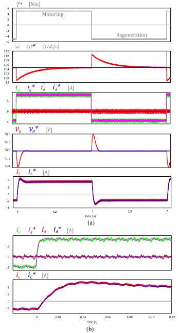
Suitable results were obtained after implementing the digital control for the bidirectional DC-DC converter as well as for the control of the SPMSM. Figure 7 shows in detail the results for the regulation of the DC-link voltage (VH) besides the rotor speed (w) that were successfully controlled according to the required references (VH *=500[V] and W*=1000[rpm]= 104.72[rad/s]) for motoring as well as for regeneration purposes, in one hand and on the other hand, the inductor current (iL) is also appropriately regulated and flows from the battery to the SPMSM when the load torque (TL *) is positive and it flows from the electric machine to the battery when the load torque is negative, i.e. a regeneration condition. Figure 7b shows a magnifier of the id and iq results, there it also can be checked that the quadrature current iq (which is proportional to the torque) successfully follows the reference iq * while the direct current id is controlled to zero.
6. CONCLUSIONS
The power converters and the proposed control schemes involved an electric traction application have been designed and successfully verified. The control logic was developed to be directly run on a commercial embedded system. The proposed cascade control schemes in which PI-regulators were implemented, exhibited successful results when controlling the high-voltage DC link and the torque-speed regulation of the SPMSM by means of the vector control strategy; suitable responses were attained for steady-state and during transients. The employed power topologies and control strategies proved to be a versatile solution for both operations: motoring and regeneration conditions.