I. Introduction
For any feedback control systems, actuator/sensor and system faults may degrade control performance or even destroy the stability of the overall systems 1. It is, therefore, significant to enhance the system reliability not only by improving reliability of individual components but by designing state-of-the-art control strategy to compensate the effects of faults to the overall system as well. Thus, the development of the Fault-tolerant Control (FTC) has received considerable attention during the last two decades 2, 3, (4. Recent attention has turned to methods of handling nonlinearity in FTC considering specific system structure 5, 6. To handle nonlinear system dynamics soft computing techniques can be used to the control such a system 7, 8, 9.
Existing FTC approaches based on soft computing techniques may be either passive or active approaches. The passive approach takes care of the faults as system uncertainty using robust control, in contradictory the active methods work on estimate fault magnitudes and use to compensate the fault effects with the closed-loop control system using Fault Diagnosis and Identification (FDI) algorithm. Although PFTC might achieve acceptable control performance 5, 6, 11 and 12 it cannot obtain local fault magnitude information and type of faults.
The traditional active FTC approach works on FDI that generates information about the occurrence and severity of the fault which could be used to reconfiguration of a close-loop system based on analytical redundancy 13. However, to obtain correct fault information one important goal is to achieve a suitable fault tolerance and an acceptable control performance.
The liquid level is a crucial process parameter for any chemical industries. Conical tank system is widely used in food processing industries, cement, and concrete process industries, wastewater treatment plant. Therefore, controlling liquid level parameter in the conical shape tank is major parameter. Control the level of liquid in a conical tank presents a challenging problem due to its constantly changing cross-section that results in non linear behavior of the system. Hence, control of liquid level is an important and challenging task in different industries.
To handle the problem of nonlinear system with actuator and system faults, in recent years, many FTC approaches have been developed, see example 14, 15, 16, 17, (18 and reference therein. The authors design FTC for SISO and MIMO nonlinear system subject to actuator and sensor faults using soft computing techniques as well as strict feedback control method. To design FTC strategy for nonlinear system artificial intelligence techniques have been used in the past decade, for instance 7, 8 and 10. In 19, 20, (21 investigate the FTC scheme for large-scale nonlinear system to tolerate the multiple additives and intermittent fault nature.
To improve the system reliability and profitability of the plant, significant research has been done to developed FTC strategy in recent years for interacting and non-interacting level control system. In 22 author has designed a passive fault tolerant algorithm for a single-tank non-interacting level control system using fuzzy logic subject to system fault and process disturbances, also it has been verified on the experimental setup. In 23 due to the highly nonlinear behavior of the three-tank in series interconnected system Non-linear Model Predictive Control (NMPC) is implemented to achieve the servo plus disturbance rejection and regulatory control in presence of changing valve position which serves as the disturbance input. In 9 authors has designed fault-tolerant algorithm for a DTS200 three-tank interacting system considering fault sources, (process disturbances, input conditions, and disturbances through inter-tank connections) are experimentally verified. Authors of 24 have used Model Predictive Control (MPC) and fuzzy logic to design a fault tolerant control (FTC) scheme for a three-tank benchmark system to accommodate two faults. In 25 distributed fault tolerant scheme is implemented on two-tank benchmark system with faults.
In recent years, artificial intelligence (i.e. fuzzy logic, neural network, etc.) based control techniques has been developed for controlling the level of multi-tank system, successively implemented and discussed in literature 28, 29, 30, 31, 32, (33. The fuzzy adaptive smith predictor is used to control three-tank system with delay in 28, fuzzy adaptive PID improves the resisting ability and adaptive ability of the system to random disturbances, and smiths predict control overcomes the delay characteristic of the control object. The fuzzy logic control approach is implemented on three-tank level control system in which Look-up decisions tables methods are used with fuzzy control and is practically validated in 29. Also in 30 model based predictive control algorithm design for the class of nonlinear system is presented. In 31, 32, (33 intelligent level control techniques are investigated for multi-tank system using fuzzy logic, in 31 interval type-2 fuzzy logic approach design for removing system uncertainty is presented, whereas in 33 a novel approach is developed using aggregation of fuzzy controllers for multivariable system.
The remainder of this paper is organized as follows. In Section II, the problem statement and preliminaries are described. Passive FTCS design is explained in Section III. Subsequently, the simulation of passive FTC approach is evaluated in Section IV. Finally, the discussion and conclusions are drawn in Section V and VI, correspondingly.
II. Problem Statement And Preliminaries
Conical tank level control system
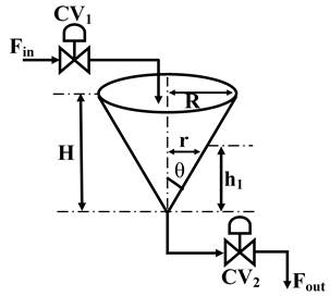
Fig 1. presents a conical tank level control system (non-interacting) in which the main objective is to maintain level (h 1) in the conical shape tank by controlling the manipulated variable inlet flow rate F in .
where, F in is the inlet flow rate of the tank, F out is the outlet flow rate of the tank, R is the maximum radius of the conical tank, r is the radius of the conical tank at steady state, H is the maximum height of the conical tank, h 1 is the height of the conical tank at steady state, and A is the area of the conical tank.
Two-Tank Conical Non-Interacting Level Control System (TTCNILCS)
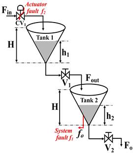
The TTCNILCS contains two identical conical shape tank connected in series. The prototype structure of TTCNILCS is depicted in Fig 2. The conical tank level control system is widely used in food processing, chemical, and metallurgy industries due to its shape; also it is used for practical demonstration as well as to developed control algorithms for research purpose due to its nonlinear behavior.
The TTCNILCS process described as, the liquid inflow F in is delivered into the Tank 1 via a pump and outlet flow F out from Tank 1 is inlet flow to the Tank 2 and outlet flow of Tank 2 is F o through the two control valves V 1 and V 2, respectively. The two conical tanks under consideration have the same cross-sectional area. The main objective in mathematical modeling is to find the transfer function for the system that is a relation between output variable h 2 (s) (liquid height in Tank 2) and input variable F in (s) (inlet flow to Tank 1). In this case, the manipulated variable is F in and controlled variable is h 2.
TTCNILCS prototype model
The mathematical model is derived separately for both conical tanks as follows.
From Fig 1.:
At any height (h 1) of Tank 1:
For Tank 1 the mass balance equation is given by following relation 26:
The area of the conical Tank 1 at height (h 1) and Tank 2 at any height (h 2) are given as follows:
Similarly, for Tank 2 the mass balance equation is given by following relation 26:
Where, outlets flow of Tank 1 and Tank 2 are given by:
Now solving and linearizing (4) and (6) at a given operating point using Taylor’s series expansion, the standard mathematical model for the TTCNILCS can be obtained as follows:
Table 1 System parameter of TTCNILCS
| Parameter | Symbol | Value |
| Total Height of the tank | H | 90 cm |
| Top Radius of the Tank | R | 15 cm |
| Inlet flow rate of Tank 1 | F in | 0.00278 cm3/s |
| V1 Valve Co-efficient | β1 | 5 cm2/s |
| V2 Valve Co-efficient | β2 | 4.25 cm2/s |
| Steady state tank 1 | h 1 | 45 cm |
| Steady state tank 2 | h 2 | 32 cm |
| Gravitational constant | g | 9.82 m/s2 |
| Process Delay | τ d | 0 s |
By considering the above operating process parameters, the linearized model of the proposed system is expressed as follows:
From the model of TTCNILCS, PFTC is designed and simulation is carried out subject to actuator and system faults.
Fault scenarios considering in TTCNILCS
In this paper, system (leak) fault represents situations where the tank-level is drastically reduced in tank 2 and control valve is unable to intercept the faulty situation and hence control performance is degraded. The second actuator fault represents a situation where the control valve (CV1) facing the problem of loss of effectiveness and hence (CV1) is not opening as per controller signal. Also, process disturbances are required to be considered in TTCNILCS as these circumstances may lead to performance deterioration.
III. PFTC Design For TTCNILCS
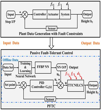
For designing PFTCS, soft computing methods are used. Neural Network (NN) and PID controller are used to design robust controller structure to tolerate the system /actuator fault and process disturbances. PFTCS gives remarkable results in the occurrence of system and actuator faults in the system. The PFTCS scheme is presented in Fig 3. 27.
PID controller transfer function is given as follows:
where G c is PID controller transfer function, K p is propotional controller gain, K i is integral controller gain, τ i is integral time, and τ d is derivative time.
The PID controller parameters; proportional gain K p Integral gain K i , and derivative gain K d are identified using manual tuning method. The constants for the PID controller are given as K p = 36.59, K i = 0.1450, and K d = 1512.19.
Performance of the system with PFTCS and without PFTCS is summarized in terms of Mean Square Error (MSE), Root Mean Square Error (RMSE), and Integral Absolute Error (IAE), which are defined as follows:
where X i is the vector denoting values of n number of predictions, X i is a vector representing n number of true values, n is the number of samples, and e is an error.
IV. Simulation Results
Simulation results with an abrupt fault in nature
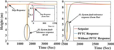
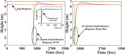
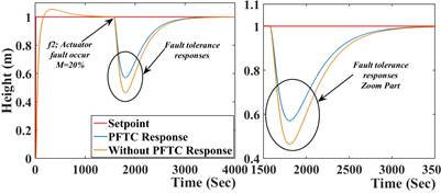
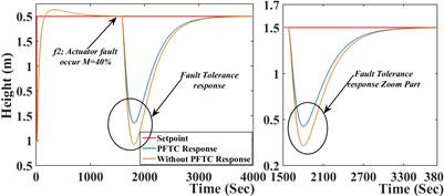
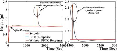
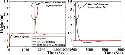
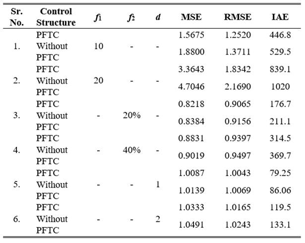
To validate the proposed PFTC scheme subject to system/actuator fault and process disturbance multiple simulation done with different fault magnitudes and abrupt nature. The results are tabulated in Table 2. and Table 3. The error indices MSE, RMSE, and IAE defined from (13) to (15), which indicate the performance degradation as the number of pre-considered faults increases. The simulation is carried out in sequential (i.e., single fault, two fault at same time), the comparative results are presented from Fig 4., Fig 5., Fig 6., Fig 7., Fig 8., Fig 9., Fig. 10. The resulting figures are clearly showing that proposed PFTC scheme gives batter control performance and system stability as compared to a system without PFTC. The PFTC scheme gives acceptable regulatory control performance subject to two faults and process disturbances. Fig 4., Fig 5., Fig 6., Fig 7., Fig 8., Fig 9. show the PFTCS responses of TTCNILCS considering the system (leak) actuator faults and process disturbances in different combinations.
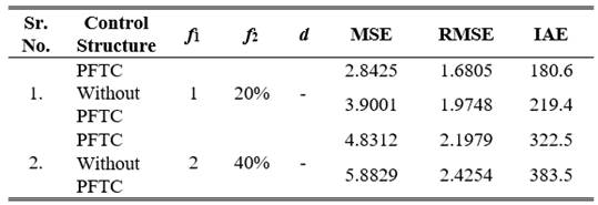
The comparative error result is shown in Table 2. in terms of MSE, RMSE, and IAE errors, which clearly indicates that the implemented passive FTCS is better when a fault occurs in the system as compared to a system without implementing a passive FTCS. For verifying the robust nature of the passive FTCS in simulation, two faults are applied into the system at the same time, the response of passive FTCS for this condition is shown in Fig 10. and the error results are given in Table 3.
*f1 denotes system fault, f2 denotes actuator fault and d denotes process disturbances.
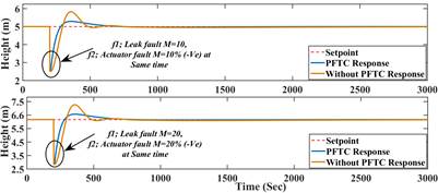
Fig 10 PFTC performance comparison with system (leak) and actuator faults occurs (abrupt in nature) at same time.
*f1 denotes system fault, f2 denotes actuator fault and d denotes process disturbances.
System control performance with passive FTCS and without passive FTCS are shown in Table 2. and Table 3., respectively, which clearly shows that passive FTCS gives the better response as compared to a system without passive FTCS. TTCNILCS performance is abruptly degraded when the magnitude of different faults is drastically increased without implementation of passive FTCS scheme. The system/actuator fault considered as abrupt in nature. The simulation is carried out for different cases such as single fault, two faults, and when a process disturbance occurs in the system. In Fig 10. a comparative response of PFTC and without PFTC scheme is presented when the system and actuator fault occur in the system at same time instance. Thereafter the PFTC control performance is shown in Table 3. using different error indices. The proposed passive FTCS scheme is capable to accommodate two faults with process disturbances. The main advantage of the proposed scheme is incorporating soft computing technique (i.e., Artificial Neural Network) to design the controller, hence there is no need to find out fault knowledge (i.e., type of fault and magnitude) also the computation time is less as compare to AFTC.
Simulation results with incipient fault in nature
Proposed PFTC strategy is tested and verified on TTCNILCS for incipient nature of the system (leak fault) and actuator faults. Fig 11. establishes the comparison between PFTC and without PFTC scheme subject to system fault f1 in different fault magnitudes with incipient in nature, which clearly shows the effectiveness of the proposed PFTC strategy.
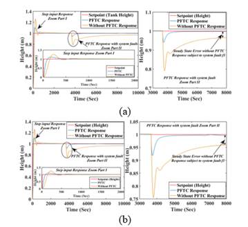
Fig 11 PFTC performance comparison subject to system (leak) fault occurs (incipient nature): (a) at low magnitude slop (b) at high magnitude slop.
Fig 12. demonstrates the comparative FTC results between PFTC and without PFTC scheme subject to actuator fault f2 (Final control element (CV1) partial failure or choke up) occurs with incipient in nature, PFTC scheme gives superior response as compared to without PFTC scheme considering the steady-state and transient response. The comparative error results with different indices are presents in Table 4. for incipient nature of system and actuator faults.
Simulation results with incipient fault in nature
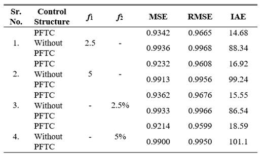
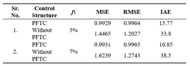
The proposed approach implemented in TTCNILCS subject to (-ve) sensor bias fault. In Fig 13., responses when abrupt nature sensor bias faults introduce in TTCNILCS with two different magnitudes. Two controller approaches are compared and error calculation is illustrated in Table 5. The proposed controller is tested with abrupt faults occurrence (sudden change).
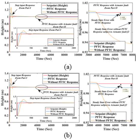
Fig 12 PFTC performance comparison subject to actuator (leak) fault occurs (incipient nature): (a) at low magnitude slop (b) at high magnitude slop.
*f1 denotes system fault, f2 denotes actuator fault both faults having incipient nature (Increasing magnitude).
Simulation results with incipient sensor fault in nature
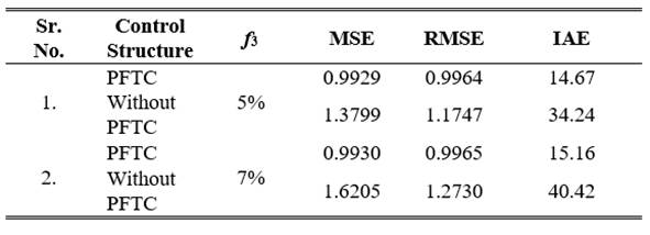
The control responses are shown in Fig 14. reveals the TTCNILCS response with and without PFTC approach. The sensor bias fault introduces into the TTCNILCS having the incipient nature (increasing of fault magnitude). The two different simulation results are derived with different fault magnitudes. The simulation and error results clearly shown that proposed PFTC scheme achieve better steady state and transient responses as compared to without PFTC. Also without PFTC is failing to achieve set point subject to sensor bias fault. With the presence of sensor bias fault in TTCNILCS 50% to 60 % steady sate error is present when proposed control scheme is not implemented while applying PFTC scheme getting zero steady state error.
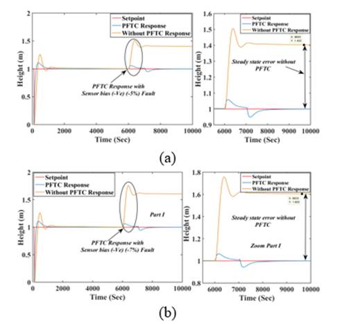
Fig 13 PFTC performance comparison subject to sensor (-ve bias) fault occurs (abrupt nature): (a) at low magnitude (b) at high magnitude.
*f3 denotes sensor fault having an abrupt nature (Sudden change in magnitude).
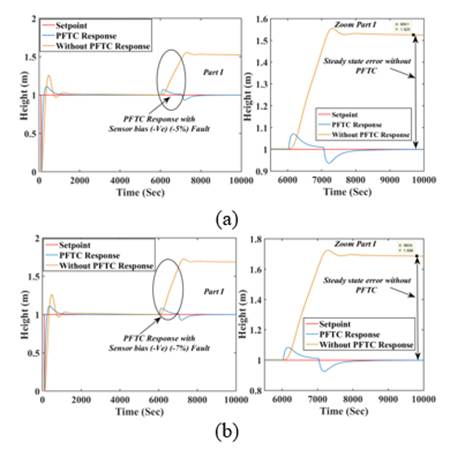
Fig 14 PFTC performance comparison subject to sensor (-ve bias) fault occurs (incipient nature): (a) at low magnitude slop (b) at high magnitude slop.
*f3 denotes sensor fault faults having incipient nature (Increasing magnitude).
Discussion
The simulation results validate the efficacy of the proposed PFTC strategy as compared to without FTC strategy in presence of sensor, system (leak), and actuator faults with different fault nature (i.e., abrupt and incipient) having different fault magnitudes. The PFTC strategy gives superior control performance in terms of steady-state and transient responses as compared to without FTC scheme. The smallest value of MSE and RMSE getting on the case of proposed scheme which proves that the proposed PFTC scheme gives almost zero steady-state error and lower value of IAE for proposed PFTC scheme represents the faster response of the TTCNILCS. From critical observing the control performance of the PFTC scheme with three faults with different nature (i.e., time-varying behavior nature), the abrupt fault nature is more critical as compared to the incipient fault nature. The abrupt nature of system and actuator faults occurring in TTCNILCS is more vulnerable to control performance without FTC scheme. The main benefits of proposed PFTC scheme are simply implemented on TTCNILCS system and give superior control performance under major three faults.
V. Conclusion
This paper has presented the passive FTC approach design for highly nonlinear TTCNILCS subject to actuator/system/sensor faults and process disturbances. The passive FTC scheme with conventional PID control and neural network techniques has been developed. It has been proved that all signals in the resulting closed-loop system are bounded and the closed-loop system is stable even after a fault occurs in the system. Also, PFTC response of TTCNILCS tracks the reference input and rejects the faults more efficiently as compared to without PFTC scheme in case they appear. The system fault is degraded system performance drastically as compared to actuator and sensor faults occur in the TTCNILCS. The proposed PFTC strategy is capable to accommodate system/actuator/sensor faults with process disturbances with acceptable control performance for the highly nonlinear system. The main advantages of the proposed approach are simple in structure, less computational burden, and efficient with and without system/actuator/sensor faults.


