


 Espanhol (pdf)
 Artigo em XML
 Referências do artigo
 Enviar este artigo por email
 Citado por SciELO
  Similares em
SciELO
Similares em
SciELO 
 Permalink
INTRODUCTION
Nowadays, energy production using wind turbines has shown an accelerated growth rate in response to climate change, for this reason government policies increasingly favor the generation of energy using renewable resources [1]. With the development of high-power wind turbines, the implementation of more reliable and efficient systems is necessary; currently the development of wind turbine technology is aimed at improving energy extraction systems [2].
The DFIG wind turbines have shown adequate performance due to their good cost-benefit reliability [3]; this machine allows manipulating the slip angle at approximately ±30% of the operating speed of the wind turbine, this consideration provides greater flexibility in speed control using techniques such as MPPT [4], [5]. For the implementation of this strategy, it is important to consider the wind speed, rotor speed, the electromagnetic torque generated by the rotation of the blades and the extracted power; as well as the mechanical and electrical components that characterize the behavior of the analyzed wind turbine. Regarding the mechanical characteristics, the model considers a system of two coupled masses as detailed in [6]; electrical characteristics include grid connection, a performance factor for the wind turbine, as well as the power converter [7].
The control strategy implemented consists of direct speed control in a DFIG 9 MW wind turbine, considering the LSS as an input variable to improve the extraction of power measured as a function of C p . For the simulation of the model, the Matlab-Simulink and FAST software have been used. It allows to represent the operation under more realistic conditions considering aeroelastic aspects. Regarding the validation of results, the controller has been subjected to test signals referred to nominal "C" _"p" [8], [9], [10]. In order to evaluate the responsiveness of the controller, a white noise signal has been incorporated to the wind speed input signal and mechanical disturbances.
In section two the components included in a DFIG wind turbine are detailed, as well as the mechanical and aerodynamic parameters that make up the turbine for the simulation of DSC. In section three the control strategy and simulations based on FAST and Matlab-Simulink are described [11], and [12]. Finally, the results are presented in section four.
DFIG SYSTEM DESCRIPTION
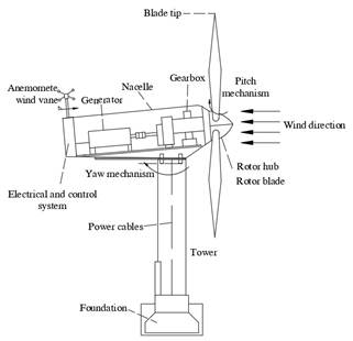
The proposed DFIG wind turbine system includes all the mechanical and electrical components necessary to evaluate the performance of the model under normal operating conditions. The parameters considered to obtain the maximum power point the model include: the wind turbine blades, the turbine nacelle, the box of gears, as well as the tower that supports the generator and the connection to the grid. The systems involved in the electrical generation: aerodynamic model, mechanical system, electrical, and control system [4], [6], [13].
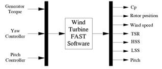
The proposed wind turbine model, as well as its interaction with the systems, can be seen in Fig. 1.
Mechanical Model
The mechanical model of a wind turbine is commonly approximated to a two-mass power train model [14]. Fig. 2 displays the representation used for the model in this proposal.
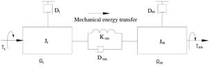
In Fig. 2, the high-speed component related to the generator rotor is on the right side, while the low-speed component related to the turbine is located on the left side. From the general mechanical model and applying Newton's second law, the equations of approximate the behavior of the mechanical model are extracted [6], [7]; the moment of inertia and the torque generated are shown in equation (1):
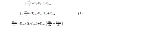
where Ω m is equal to the High Shaft Speed (HSS) or the angular speed at the machine side, Ω t is the LSS or the angular speed at the turbine side, the T em is the electromagnetic torque, and K tm and D tm are factors related to the friction and inertia, respectively. The model can be simplified by neglecting the damping coefficients ( D t , D m , and D tm ); consequently, it results in a two-inertia model ( J t , and J m ) and the stiffness constant ( 𝑲 𝒕𝒎 ) [6].
Pitch Angle Control
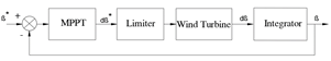
The Pitch angle controller allows to regulate the position of the blades for turbine’s speed control. Each blade has its own pitch regulator, the independence of the controllers allows the control of each blade separately; to move the blades it is common to use hydraulic actuators [6]. The control strategy implemented in the regulators is shown in Fig. 3, where a traditional PI controller provides a reference applied to the turbine model, the angle of inclination is calculated by integrating the variation of the angle. For the implementation, it is necessary to measure the wind speed, the HSS, as well as the angle references to regulate the speed of the turbine in an adequate way [6], [15].
Wind Turbine Aerodynamics
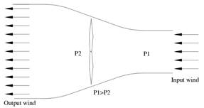
The ability to extract power from the wind turbine depends directly on the rotation speed of the turbine, thus the system converts wind energy into rotational energy. In the conversion process there is a variation in the pressure exerted by the air as can be seen in Fig. 4, this behavior allows a high energy extraction capacity. This representation indicates that the pressure after the wind enters the wind turbine swept area decreases, the remaining energy is transferred to the turbine by the rotation of the blades.
The expressions that relate the behavior between the aerodynamics and the power extracted from a wind turbine are based in terms of: Cp, blade length, wind speed and air density [6], [15]. As a result, the extracted power can be formulated by the relationships described in equation (2):

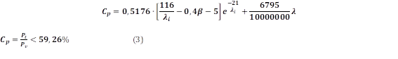
where P r is the mechanical power of the rotor in (Watt), 𝑽 𝒘 is the wind speed in (m/s), ρ is the air density in 𝑲𝒈 𝒎 𝟑 , C p is the rotor power coefficient, 𝒓 is the distance from the center of the rotor at the tip of the blade, or the blade’s length in (m), w is the angular velocity of the rotor in 𝒓𝒂𝒅 𝒔 , β is the pitch angle of the blades in (degrees), λ is the tip speed ratio (TSR) which is defined as the ratio between the speed of the tip of the blades and the speed of the wind over the rotor [16], [17]. For a wind turbine, the Betz limit establishes that the maximum generation capacity is 59,26% of the energy transferred. This limit is called the power coefficient and it relates the length of the blade to its angle of incidence β [15]. The expression is defined in equation (3):
INDIRECT SPEED CONTROL MODEL
The main benefit of applying the DSC technique is to improve the response capacity of the wind turbine in terms of C p ; the controller estimates the speed of the turbine through the TSR, which is related to 𝝀. For speed estimation, the DSC control starts with T em , consequently, a state observer capable of estimating the torque which is directly related to the optimal operating speed. The equation that allows describing the optimal reference speed 𝜴 𝒎_𝒓𝒆𝒇 is shown in equation (4) [4], [6]:

where T t_est is the estimated aerodynamic torque, N is the gearbox ratio, and 𝑘 𝑜𝑝𝑡_𝑡 is the adjustment constant that allows for the optimal electromagnetic torque. The implemented control scheme is shown in Fig. 5. To calculate Ω m_ref it is necessary to describe the T t_est and k opt terms. For the proposal, the control technique calculates the maximum Cp value, when this occurs the torque can be expressed with equation (5); consequently, the value of k opt can be calculated with equation (6).

Indirect Speed Control Implementation
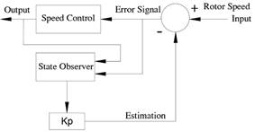
The implemented DSC method seeks to estimate the aerodynamic torque T t_est which considers the angular speed of the turbine as an input signal. With the estimated torque the controller can regulate the electromagnetic torque control signal with faster dynamics. For the calculation of the error signal the estimation considers a proportional gain Kp. For instance, in this analysis the gain Kp is unitary [4], [6]. The state observer proposal is shown in Fig. 6.

For the implementation of the DSC within the DFIG wind turbine, LSS is considered as an input signal, together with equation (5), i qr can be calculated by means of equation (6) in terms of the electromagnetic torque generated as shown in equation (7), [6], [15].

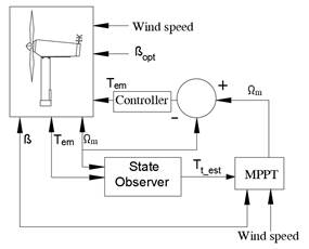
Where L m is the mutual inductance and L s is the stator inductance, p is the pole pairs of the wind turbine and Ψ s is the electromagnetic flux of the stator. A representation of the direct speed controller for the proposed DFIG wind turbine is shown in Fig. 7.
With respect to FAST, the software models the wind turbine with rigid and flexible elements, this allows evaluating the performance of the controller and simulating the aeroelastic behavior of the turbine. In Fig. 8, you can see the FAST model [11] implemented in Matlab-Simulink [12] to obtain an array of multiplexed output variables that interact directly in the proposed controller model.
SIMULATION RESULTS
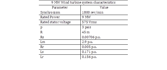
The next subsection shows the DSC simulation with uncorrelated white noise added to the input wind speed signal to test the robustness of the system to naturally or externally produced oscillations. Regarding the electrical and mechanical parameters of the implemented wind turbine, Table 1 describes the data used for the model [6].
Variable Wind Speed with Transitions
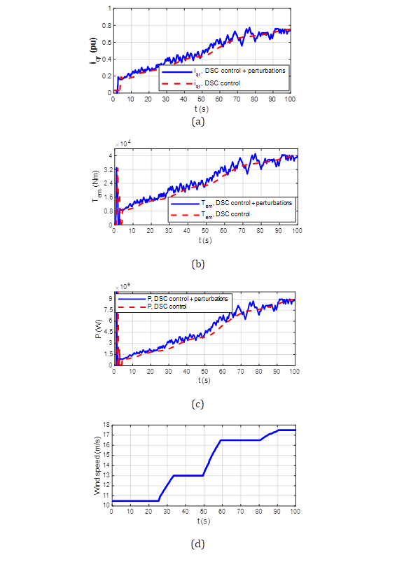
Fig. 9 shows the behavior of the DFIG wind turbine with an input signal with progressive variations. Thus, with a deterministic signal, the response capacity of the controller against disturbances can be evaluated; step functions are traditionally used to evaluate the response of the system with drastic variations in the system input. The wind speed input signal varies between 11 and 17,5 m/s as shown in Fig. 9 (d). Regarding the extracted power, the model shows an extraction of approximately 9 MW which indicates that the controller works properly despite incorporating a noise signal. The response of Cp according to the restrictions mentioned in the previous sections reaches approximately 0,44 %. Fig. 9 (a) shows the performance of the reference current and Fig. 9 (c), displays the adequate generated power recovery despite the oscillations of the error signal generated by the disturbance.
Variable Wind Speed with Realistic Input
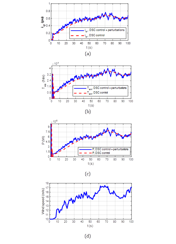
To ensure good response dynamics under normal operating conditions, the controller was subjected to a realistic input signal varying between 10 and 17,5 m/s as shown in Fig. 10 (d). Regarding the extracted power, the model is able to respond quickly in terms of power extraction as shown in Fig. 10 (c). Regarding the power coefficient, the controller can respond with a faster dynamic against disturbances, which indicates a more robust system as shown in Fig. 10 (g).
CONCLUSIONS
In this research, the DSC has been implemented by using FAST and Matlab for a 9 MW DFIG wind turbine. Compared to the control with and without disturbances, the results highlight an important improvement because of the correct selection of optimal TSR and maximum C p when calculating the optimal torque constant at the controller stage. This implementation also considers the initial LSS speed and inertia which produce an oscillation during the first 20 seconds of simulation. Nevertheless, after that period of time, the rotor speed becomes steady and closer to the nominal value. The considered simulations have the intention of demonstrating the capability of this technique to provide a fast response, even in the presence of disturbance in the system i.e. the LSS. Furthermore, the pitch controller is able to limit the speed of the shaft properly. The power and speed reach are close to their nominal values and these simulations demonstrate the correct operation of the wind turbine in partial load conditions.
The DSC strategy based on the Luenberger state observer has allowed the system to operate with a better power extraction and C p . Although the system is unstable during the first seconds of simulation due to the initial conditions, it rapidly reaches the optimum values. This means more active power generation and more reactive power absorption of wind turbine. The advantage of this technique is that the observer does not require any additional hardware implementation since it exploits common wind turbine signal measurements such as the HSS, the wind speed, torque, voltages, and currents. For further implementations, it can be increased the number of inputs intended to improve the accuracy of the controller.

