


 Espanhol (pdf)
 Artigo em XML
 Referências do artigo
 Enviar este artigo por email
 Citado por SciELO
  Similares em
SciELO
Similares em
SciELO 
 Permalink
INTRODUCTION
The production of energy based on renewable sources such as wind energy, is a subject of continuous study due to the benefits they provide to daily activities. The increase in demand in its generation, as indicated in [1], [2], demonstrates a reality of the energy need, and together with the possibility of adaptation in the environment, wind energy makes possible the development of new technologies and increasingly effective control techniques for the extraction of power from the air in models of different scale adapted to environmental conditions. In this context, the recurring control methodologies immersed in different aspects of the wind turbine systems, contribute to its correct operation.
One of these strategies, such as the MPPT, allows the regulation of the optimum operating speed of the turbine [3]. This principle is widely used for its importance in optimizing the extraction of power provided by the wind, which, measured in terms of C p , is an indicator of the performance of the wind turbine. In this research, the control strategy is intended to find its optimal C p value and modify the command for the power electronic converter, demonstrating the effectiveness of the technique in power generation including disturbances.
According to the literature [4], [5], [6], and [7], a variety of methodologies based on the MPPT principle in order to extract the maximum power, are developed, such as: Indirect Speed Control (ISC), Tip Speed Ratio (TSR), Artificial Neural Network (ANN), Power Signal Feedback (PSF), Hill Climb Searching (HCS), Optimal Torque (OT), and Fuzzy-based controllers. These controllers are widely discussed in wind turbines for different generator configurations. These techniques use often DFIG electric machines. This is because of the advantages they offer about quality and efficient energy production, low installation costs, and operability in a more flexible range of speeds [2], [8].
In this research, the MPPT technique is developed with the use of a Fuzzy controller, which operates based on the mechanical and electrical characteristics of the wind turbine, forming a direct speed control (DSC) model, supported by a PI in the stage of estimating the current component on the rotor side, i qr . The principle of operation consists of estimating the optimum electromagnetic torque and consequently the extracted power, regulating the speed of the turbine, and in this way, making it possible to reach and maintain its ideal C p operating value around it, reacting to changes in the input wind speed and mechanical disturbances that may affect the system. The use of analysis and simulation software for the correct modeling of the wind turbine was necessary, for which, FAST from NREL [9], where the turbine dynamics is estimated, and Matlab-Simulink [10] where the electrical machine is represented and the controller is implemented, they are coupled, working together to validate the results in consideration of more precise and detailed parameters and characteristics of the model. With this approach, the responses of the system dynamics are obtained, validating the strategy based on the correct behavior of the variables involved, evidencing the robustness of the control.
The development of this study points out important aspects that support the method and the working model, such as in section 2, where the aerodynamic principle that governs the operation of the wind turbine is explained, and in section 3 that contextualizes the mechanical representation based on a powertrain concept. In section 4 the model is complemented with the description of the electrical part regarding the DFIG generator. In section 5 the effect of disturbances in the system is analyzed and the MPPT control method is introduced, coupled with the characteristics of the 9 MW wind turbine model. Subsequently, the results obtained in section 6 are presented, with the incorporation of the control technique, analyzing the viability of the proposal.
WIND GENERATOR AERODYNAMICS
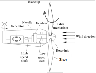
The conversion of wind energy goes through a set of stages from the incidence of the wind on the blades to the generation of electrical energy. In Fig. 1 the generic model of a horizontal axis wind turbine with its different parts is shown.
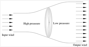
The first step of this conversion involves the capture of energy through the rotating mechanical elements of the turbine, causing a change in pressure, as seen in Fig. 2, between the incoming air and the area immediately behind the blades. The air flows through the turbine sweep area, resulting in a decrease in pressure due to energy transformation [11], [12], [13]. During this process, elements intervene that affect the amount of power that can be extracted from the air by the turbine, such is the case of the length of the blades R in (m), the wind speed V w in (m/s), the air density ρ in (kg/ m 3 ) in the turbine installation area, the rotational speed of the turbine ω t in (rad/s) and the angle of rotation of the blades β in (deg). With these characteristics, the mechanical power P in (Watt) produced in the rotor can be calculated according to the equation (1):

where, C p indicates the value of the power coefficient and λ is the TSR factor, calculated according to the equation (2), which indicates the existing speed ratio at the end of the blades and the speed of the captured wind that causes the movement.

The following conversion stages occur in the mechanical gearbox arrangement and finally in the electric generator, which are detailed in later chapters.
Operating Zones of a Wind Turbine
In consideration of the magnitude of the wind speed that intercepts the turbine, the operating mode of the wind turbine differs. In this context, the operational speed range is delimited, on the one hand, by the cut-in wind speed from which the wind turbine produces power and, on the other hand, by the cut-out wind speed, which establishes the limit of maximum operating speed to protect the entire system [14]. In this way, as shown in Fig. 3, the working zones of the wind turbine are determined, which correspond to the stop zone, zone of maximum power extraction, and pitch angle control region [6], [15].
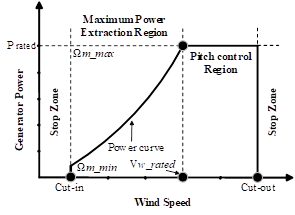
It is important to establish the operating zone on which the system works, which in the case of the present research is the extraction region of maximum power, where the optimum C p is reached through the control of the rotor speed.
Power Coefficient Representation
The power coefficient is a non-linear factor delimited by Betz's law in approximately 0,59, that establishes the condition of effectiveness in the conversion of wind energy by the wind turbine, which is found in the function of β and of the TSR in equation (2) [15], [16]:

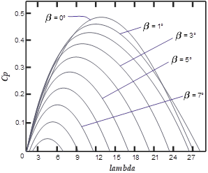
Each wind turbine has its own C p curve, defined according to its physical characteristics, which contribute to the operation of the turbine within specific operating parameters, and it is expressed mathematically via equation (3) [13], [17]:

where c 1 … c 8 are the coefficients that establish the particularities of the wind turbine C p . This mathematical expression can be graphically represented by a C p vs TSR curve, Fig. 4, in which, at different parameters, the influence of the TSR on the estimation of the C p is appreciated in greater detail, which in turn always depends on the wind speed and pitch angle input signal.
Optimal Operating Parameters in Power Extraction
Introducing the analysis in zone 2 of operation, the maximum possible power to be extracted in the respective range of wind speeds requires that the wind turbine works with the optimal parameters of TSR λ opt and the orientation of the pitch angle β opt , responding, consequently, to the scope of an ideal torque T ideal dependent on the rotor speed ω r , for which, the maximum possible value of the power coefficient C p.max is required; all this observation is represented by the following equations [13], [18]:


MECHANICAL REPRESENTATION OF THE WIND GENERATOR
Once the wind energy is captured, movement is generated in the turbine, which must be transmitted to the generator. This link stage is the powertrain, a fundamental part of the structure of the wind turbine that allows the conversion of speed and torque from the turbine as an effect of the impact of the wind on the blades, towards the generator, allowing its rotation and generation of electrical energy.
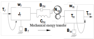
The modeling of this section can be simplified in a description of the type of two-mass structure, Fig. 5, according to the equations (6), (7), and (8), providing considerable precision in the analysis, coupled to the turbine by the Low Shaft Speed (LSS) and to the generator through the High Shaft Speed (HSS), maintaining a certain gearbox ratio N 𝒕𝒈 , in equation (9), for the correct conversion of the mechanical variables involved [19], [20]:


where the inertias J 𝒓 and J 𝒈 of the rotor and the generator, directly influence the dynamics of the system, reflected in the rotation speed of the turbine and the generator 𝝎 t and 𝝎 g . The compensation for this behavior depends on the torques involved in the low and high-speed parts T ls and T hs respectively, and on the torques of the turbine T t and the electromagnetic torque of the electrical machine T em , as well as the damping and stiffness coefficients, B and C, that can be finally negligible.
From the equations (6), (7), (8), and (9), a global expression is calculated that represents the mechanical model of the wind turbine in equation (11):

When the expression (11) is obtained, the connections of the turbine with the generator and the transmission of movement are defined, being useful for the development of a control by integrating the mechanical and electrical parts.
ELECTRICAL DESCRIPTION OF THE DFIG
To complete the energy conversion process, the electrical machine is essential. In this investigation, a DFIG generator model is used.
A notable feature of the DFIG is its dual connection. On the one hand, the stator is directly linked to the electrical grid, while the rotor is linked through an intermediate system, the back-to-back power converter, with which the conversion zones are identified in rotor side (RSC) and grid side conversion (GSC), giving the flexibility to operate within a speed range further from synchronous speed, by approximately ±30%, in addition to facilitating power control active and reactive with the use of currents 𝒊 𝒒𝒓 and 𝒊 𝒅𝒓 detailed in equations (12) to (20) [1], [2]. With this configuration of the DFIG, and using the Park transform in the d-q framework, the classical equations that govern its operation are extracted [21]:


where the fluxes in the stator and rotor are expressed as:


considering the relationships:

Where each element is referred to the respective d-q frame, being ν ds , ν qs , ν dr and ν qr voltages; i ds , i qs , i dr and i qr currents, and Φ ds , Φ qs , Φ dr and Φ qr the fluxes, both on the stator and rotor side. In the same way, R s and R r are the stator and rotor resistances, L s and L r are the stator and rotor inductances, L ls and L lr are the leakage inductances, and M is the mutual inductance.
DISTURBANCE AND CONTROL DYNAMIC RESPONSE
There are several causes that lead to the presence of disturbances that are introduced in the model of the wind turbine. The noise could affect the entire system because of the dynamics of different components. This perturbance could affect energy production. These disturbances, as mentioned in [22], and [23], can be the result of the tower shadow effect when the blades cross in front of the tower, or by wind shear, caused by a non-uniform entry of wind in magnitude and position. In addition, in [24] refers to the effect of wind speed turbulence that generates vibrations in the gearbox system.
All these variations affect the performance of the wind turbine and therefore the maximum power extraction is compromised. Due to this problem, it is necessary that the used controllers remain robust enough to cope with these effects.
Fuzzy-PI MPPT Controller Design
Due to the existence of various subsystems in a wind turbine and the complexity of operation that each one of them involves in its modeling and that of the whole, in addition to the inevitable presence of disturbances of different nature, previously analyzed, the ideal behavior during the process energy conversion is affected. With this situation, the general operation of the wind turbine presents a non-linear dynamic that negatively influences its control. Given this reality, the Fuzzy technique is implemented, being a viable option, as indicated in [25], by managing with greater precision the non-linearity of the system and the inaccuracy of the variables due to constant changes in them.
The DSC Fuzzy technique that is implemented in this study operates based on the measurement of the mechanical and electrical parameters of the wind turbine and making use of the equations (4), (5), (9), and (11)(11) to obtain an ideal speed reference of generator operation ω g .
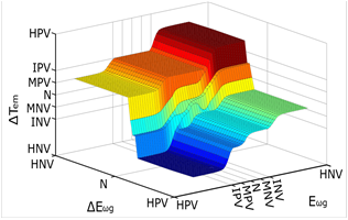
From the speed reference, it enters the Fuzzy controller its error E ωg signal and returns an alteration factor of 𝑻 𝒆𝒎 . The controller follows an estimation process based on the linguistic terms used: HNV (High Negative Variation), INV (Intermediate Negative Variation), MNV (Minimal Negative Variation), N (Null Variation), MPV (Minimal Positive Variation), IPV (Intermediate Positive Variation) and HPV (High Positive Variation), and the control rules reflected in the conversion curve in Fig. 6, making use of Generalized Bell-type membership functions.
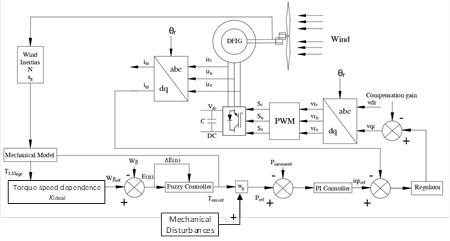
With this fuzzy logic reference, the effective speed and torque ratio necessary to follow the optimum 𝑪 𝒑 is established. From the 𝑻 𝒆𝒎 found, a power signal is calculated, which enters a classic PI controller to determine the current reference 𝒊 𝒒𝒓 with which the torque indicated by the control can be established in the machine. The integration of the entire process is presented in Fig. 7
ANALYSIS OF RESULTS
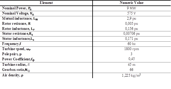
The validation of the control strategy was carried out in a wind turbine model detailed in Table 1, with the application of a disturbance signal of the white noise type, as a reference to alterations in the mechanical subsystem of the wind turbine. This condition was carried out in order to test the robustness of the controller and the response of the system to alterations in the ideal operating conditions that are actually present. The disturbances in question are reflected from the rotor speed input signal as a direct measurement mechanical variable at the control input.
In addition, two types of wind speed input were considered, both a stepped incremental signal and a realistic signal with sudden alterations in its magnitude. In this way, it is possible to verify the response of the wind turbine, mainly affected only by mechanical disturbances, as well as by the presence of disturbances caused by constant variations in the wind.
System Response with Steps Wind Speed
The first analyzed case of study involves sudden changes in wind speed, Fig. 8, established as sudden increases and additions of linear variations.
The robustness of the system with the application mainly of the Fuzzy controller is measured by detecting the power extraction capacity around the optimal operating values. The response of the model without the influence of external noise in the system is compared with the response when introducing a signal from mechanical disturbances in Fig. 9. The incoming disturbance reflects mechanical disturbances due to various factors in general, such as those analyzed in the previous section, which alter the control variables.
The control strategy shows high reliability in response to the effect of wind behavior and the influence of disturbances. As can be seen in Fig. 10, the power is generated within the average values with the presence of noise when compared with the response in an ideal behavior of the system. Similarly, the electromagnetic torque, Fig. 11, and the speed of rotation of the machine, Fig. 12, bases of the Fuzzy control, operate with a rapid reaction to sudden changes in the conditions to which the turbine was subjected.
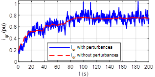
The reference current 𝒊 𝒒𝒓 , Fig. 13, by the effect of the estimated 𝑻 𝒆𝒎 , also responds quickly, allowing efficient operation of the involved variables.
Regarding the power coefficient, it remains in its maximum power extraction value, Fig. 14, with small deviations due to sudden changes in external conditions, but achieving good stabilization, reflecting the robustness of the controller in the first test of functioning.
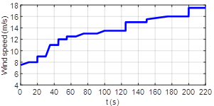
System Response to a Realistic Wind Speed
In this second test carried out, the wind speed signal, which directly influences the generation of disturbances, is recreated. The behavior of the wind in this simulation, Fig. 15, presents permanent oscillations similar to the reality due to changes in pressures of the environment.
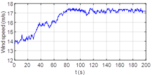
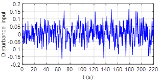
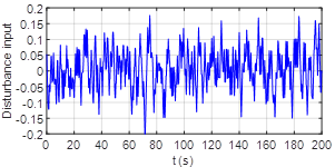
The turbulent airflow impacts the turbine and affects the conversion of energy from the mechanical elements that capture the wind. The signal of mechanical disturbances added to the system, Fig. 16, as in the previous test, defining other mechanical disturbances that occur in addition to the entry of wind, recreates a non-ideal work situation that is normal during the commissioning of a wind turbine.
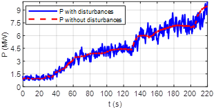
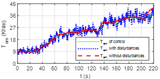
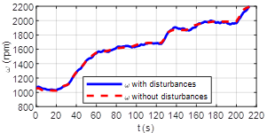
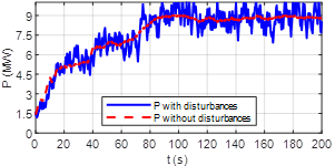
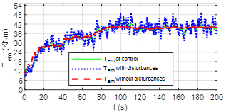
As a response of the wind generation system for this second case of study, with the presence of a greater number of alterations, it is evident that the extracted power, Fig. 17, is around the optimal values, presenting variations due to constant changes of the system conditions and the effect of inertia that delays stabilization. The electromagnetic torque also shows a similar behavior, Fig. 18, maintaining a trend in the correct follow-up of the reference given by the controller within the appropriate values.
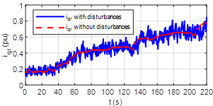
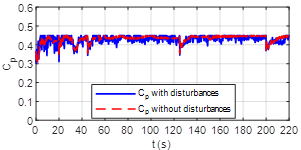
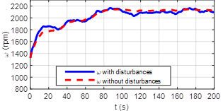
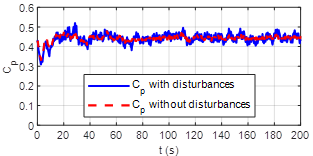
The speed of the generator, Fig. 19, is directly affected to maintain the respective relation to the 𝑻 𝒆𝒎 and achieve maximum power extraction, making this work more difficult due to the inertia of the system, but with good precision with respect to the ideal response. The current reference 𝒊 𝒒𝒓 , Fig. 20, fulfills its objective, reacting to each variation of the electromagnetic torque estimated in the controller, allowing the system to adapt to the changes caused by disturbances. Finally, the measurement of the power coefficient, Fig. 21, in harmony with the trend reflected in the analyzed variables, shows the following of the ideal value, with expected oscillations in its dynamics, due to both the dynamics of the system and the alterations in its normal operating conditions.
In this way, the robustness of the direct speed control technique is validated with the incorporation of a Fuzzy controller complemented with a PI, which allows obtaining an effective response of the system, reacting adequately to the influence of external disturbances.
CONCLUSIONS AND RECOMMENDATIONS
The existence of unwanted external factors in a wind turbine is inevitable and affects its performance directly, before which, the control systems to be incorporated must be able to operate efficiently and solve as much as possible the alterations caused by these disturbances. In this sense, the control technique presented in this study, based on the use of a Fuzzy PI controller applied in a DFIG 9MW wind turbine model, demonstrated good performance in the extraction of maximum power, integrating the mechanical and electrical elements to operate in response to dynamics that change sharply over time.
The effectiveness of the incorporation of the controller was reflected with its robustness in the measurement of the 𝑪 𝒑 , reaching a value that oscillates around its maximum possible despite the influence of noise in the system, achieving an effective response of the estimation of electromagnetic torque to regulate the speed of the turbine to the necessary magnitude of optimal operation depending on the conditions to which it was subjected.
The analyzed variables that intervene in the controller, as well as those influenced and necessary in the modeling of the wind turbine, as evidenced throughout the investigation, react quickly and with sufficient precision to the effects of the disturbances of wind and noise introduced, giving validity to the control method used.
The evaluation of the controller under the influence of electrical alterations and different network conditions is recommended for subsequent studies within the line of research dealt with, to verify the robustness of the method, as well as the use of other examples of generators used in the production of wind energy.

