


 Inglés (pdf)
 Articulo en XML
 Referencias del artículo
 Enviar articulo por email
 Citado por SciELO
  Similares en
SciELO
Similares en
SciELO 
 Permalink
Introduction
The evolution of the industry prompts the adoption of novel strategies, incorporating materials like structural steel for various applications (Ostergaard et al., 2020). In any industry, ensuring safety and comfort in the work area is paramount, with special consideration for confined spaces that demand meticulous organization (Schrogl et al., 2020). Folding structures find utility in temporary facilities or those requiring relocation. Comprising rigid elements interconnected by sets of nodes, these mechanisms facilitate expandable and contractible movements. Typically, these nodes are positioned at the ends of the elements, usually rigid bars, and occasionally at their midpoints, providing a certain degree of freedom to the components (Yamaoka et al., 2019). Regarded as one of the most efficient approaches, collapsible structures excel in terms of installation, transportation, and functionality.
Bhooshan et al. (2020) conducted a comprehensive particle study on folding work tables, highlighting their versatility as furniture adaptable to various environments, ranging from office spaces to workshops. The standout feature of these tables lies in their foldability, facilitating convenient storage and transport. Constructed with robust materials, these tables ensure stability and durability. In idle moments, they efficiently fold up, minimizing spatial requirements, an especially advantageous trait in constrained environments. Cruz (2019) affirms that there are several design methodologies for folding structures, suggesting the potential development of traction graphical methods to enhance motion control simulations. Addressing challenges like the intersection problem during the folding and unfolding process necessitates employing thickness adaptation techniques in the design field. Resolving such issues is imperative for advancing prefabricated structural systems. The overarching goal of designing folding structural systems is to optimize limited space, involving comprehensive studies on the materials used. Furthermore, proposing innovative folding techniques inspired by improvements in people's daily lives is a valuable avenue for exploration (Epp, 2020).
Preedawiphat et al. (2020) conducted mechanical investigations on A36 structural steel, an alloy composed of iron and carbon with a percentage ranging from 0.8 to 2 %. This low-alloy steel is extensively utilized in construction and various industrial applications, meeting the specifications set by the American Society for Testing and Materials (ASTM). Due to its alloy composition, A36 structural steel exhibits a remarkable capacity to support structures in diverse spaces where its use is required. Carneiro et al. (2019) delved into the service life and properties of A36 structural steel, highlighting its tensile strength of 400 MPa. Known for its commendable weldability and formability, A36 structural steel is well-suited for a variety of applications. Beyond its common use in structures like buildings, bridges, platforms, and other infrastructure, it finds application in manufacturing machinery and equipment components, such as beams, plates, and structural sections. The combination of versatility, strength, and ease of forming renders it a favored choice in the construction and manufacturing industry.
Computer-aided design (CAD) serves as a versatile tool across various engineering domains. Specifically, architectural modeling software within the CAD framework is employed for the creation and modification of three-dimensional and two-dimensional models representing real-world objects. In a study by Erazo-Arteaga (2022), the focus was on investigating computer-aided design and digital manufacturing methodologies in product development within the Latin American context. CAD software facilitates the virtual construction and modification of new parts or products swiftly, eliminating the need for physical prototypes. This tool significantly expedites work processes, concurrently minimizing errors in the product design, thereby enhancing efficiency and overall quality. Notably, designs created within the CAD platform can be stored and transported electronically, facilitating easy manipulation and visualization at any time. On the other hand, Computer-Aided Engineering (CAE), as defined by Khan & Rezwana (2021), serves as a tool for creating and developing elements through comprehensive evaluations. These evaluations span static, dynamic, fluid, thermal, electromagnetic, and acoustic analyses, all performed using computers. In a study by Berselli et al. (2020), CAD and CAE tools were scrutinized in the context of project-based learning, underscoring the importance of studying mechanical devices in a parametric environment. This emphasis on education aligns with its subsequent practical application in the industry.
Numerical analysis involves the exploration of algorithms that mathematically model the numerical outcomes of problems across diverse domains of human knowledge (Benzi, 2021). Simulation, on the other hand, involves the emulation of the operation and evolution of real-world processes or systems over time. From the perspective of numerical analysis for the current millennium, Upadhyay et al. (2021) emphasize the extensive use of simulation in industry. This approach enables the identification, development, and controlled testing of the various processes integral to industrial operations. Furthermore, modeling holds significant value in terms of repeatability, allowing identical or varied launches in diverse executions. A design analysis system, as outlined by De Holanda et al. (2019), offers simulation solutions encompassing linear and nonlinear statics, frequencies, bending, thermal conditions, fatigue, pressure vessels, buckling, dynamics, as well as linear and nonlinear optimization and analysis. Complementing this, computer-aided design plays a pivotal role in generating 2D drawings and 3D parts and assemblies. It provides an extensive toolkit spanning all stages of the product improvement process, inclusive of design, simulation, manufacturing, publication, and back-end document design (Charmi et al., 2021).
Keshavan (2022) defines a folding structure as a mechanical system, consisting of interconnected elements with movable joints that transform velocities, trajectories, and forces into energies. Within this mechanical system, rigid or semi-rigid elements form mechanisms, where one component, typically the frame, remains fixed to prevent movement. Movement occurs at joints, also known as kinematic pairs (McCracken et al., 2020).
Foster-Vázquez et al. (2021) exemplify optimization in a hospital bed lifting mechanism by modifying joints and links to reduce actuator force. In the context of folding structures, a mechanism refers to the elements and connections enabling folding, unfolding, or adjustments. Various joint types exist, with hinges allowing rotational movement between structure parts being a primary example. Telescoping joints, enabling sections to slide into each other, reduce the overall length when folded (Ramezani & Dietz, 2019). Accordion folds represent a common mechanism, extending and contracting to fold or unfold the structure. Engineering folding structures involves a diverse field encompassing creative and functional solutions.
This investigation focuses on designing a folding work table, utilizing numerical analysis in CAD software to improve workshop space utilization. The document is organized as follows: the Methodology outlines the research stages, the Results section presents graphical information from simulations, and the Conclusions section synthesizes and analyzes the obtained results, explaining the scope of this work.
Methodology
The applied investigation approach was chosen as it aims to generate knowledge directly applicable to problem-solving in the manufacturing sector (Canales et al., 2017). This method was complemented by the analytical approach, viewing analysis as a mental process that dissects complexities into parts and properties, facilitating the mental deconstruction of the whole into its various relationships. Conversely, synthesis involves uniting the analyzed parts and identifying relationships and general characteristics derived from the analysis results (Falcón & Serpa, 2021). Subsequently, the analytical-synthetic method was employed to address the primary research objective, which focused on designing a folding table for optimal space utilization. In addition, computational numerical analysis was applied to generate a 3D model and conduct simulations, encompassing structural statics and kinematics of the folding table (Flores et al., 2019). The design required a kinematic analysis of displacement and translation in the components of the table mechanism. In the case of simple rotational motion, the angular position (θ) of the link is expressed as a function of time (t) by equation (1) as indicated by Ouyang et al. (2021):
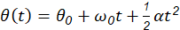
(1)
Where, θ 0 and ω 0 represent the initial angular position and angular velocity, respectively, while α denotes the constant angular acceleration. Furthermore, the angular displacement (Δθ) is defined as the change in angular position between two points in time. This displacement is determined by integrating equation (2) of angular velocity concerning time:
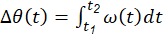
(2)
It is clear that to analyze trajectories and displacements effectively, it must begin by determining the speed at which the link moves. Angular velocity is thus defined as the rate of change of angular displacement concerning time, while angular acceleration represents the rate at which this angular velocity changes over time. Equations (3) and (4) have been applied by Ochilovich & Sadirovich (2022) to conduct the analysis:

(3)

(4)
The degrees of freedom represent the minimum number of independent generalized velocities necessary to define the kinematic state of a mechanism or mechanical system. This quantity corresponds to the number of equations required to describe the motion. For two-dimensional mechanisms, where displacement exclusively occurs in those two dimensions, the number of degrees of freedom (G L ) is computed using the equation (5) as outlined by Senapati & Chatterjee (2020):

(5)
Where n is the number of links, j 1 and j 2 correspond to the number of joints of 1 and 2 degrees of freedom, respectively. It is imperative to establish the displacement range of the supports. Given the design criterion for the table to exhibit an inversely constant angular trajectory, the trajectory, expressed as a function of the table angle, as Ponsioen et al. (2020) determined using equation (6):
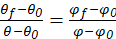
(6)
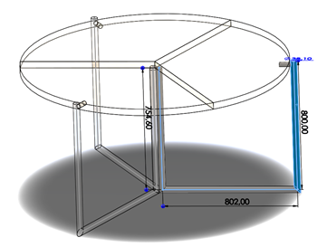
Where θ 0 and θ f are the initial and final angle of the table, and φ 0 and φ f are the initial and final angle of the motion, respectively. It's worth noting that hinge couplings were chosen, as they enable rotational movement around a fixed axis. The restriction simply involves ensuring the equality of angles between the connected links. Figure 1 illustrates the schematic design of the prototype to be analyzed, incorporating the established dimensions.
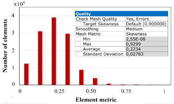
This process involves numerical analysis, a scientific discipline dealing with the construction, analysis, and application of computer methods to obtain a numerical or approximate solution for a given problem. To predict the behavior of an element under loads, the finite element method (FEM) is employed, a numerical technique for solving field problems described by a set of partial differential equations (Abueidda et al., 2019). Within mechanical engineering, FEM is extensively utilized to address structural, vibration, and thermal issues. The procedure encompasses discretizing the element, creating a mesh that divides the geometry into relatively small and simple units known as finite elements. These elements are named to emphasize that they are small relative to the total size of the model, rather than infinitesimally small (Yu et al., 2021). When working with finite elements, the software utilizes a set of simple solutions for individual elements to approximate the desired solution, such as load or stress, for the entire model. In Figure 2a, the meshing of the element is illustrated, featuring dominant tetrahedra chosen for their adaptability to special geometries and showing a detail. Figure 2b displays the mesh validation metrics. To achieve an excellent mesh, Simbaña et al. (2024) specifies that the skewness must be below 0.25, indicating that the tetrahedra closely resembles the ideal shape. In this instance, employing various meshing techniques resulted in an average skewness of 0.2234.
The proposal involves the development of structural static analysis, a method employed to ascertain a structure's response to internal loads and forces. This analysis plays a crucial role in engineering design, ensuring the safety of an element under specified loads (Seralathan et al., 2020). A widely utilized technique in this context is load analysis, which entails calculating forces and moments acting on a structure under static conditions. In this analysis, the structure is considered to be in equilibrium. To address this, Slusarenko & Rojas (2021) proposed equations (7) and (8):

(7)

(8)
Where F is the force in the x-axis and y-axis, and M is the moment. The Von Mises stress is characterized as the uniaxial stress capable of producing equivalent distortion energy to the actual combination of applied stresses. This approach enables the treatment of combined multiaxial forces, encompassing both normal and shear stresses, s if they were pure axial stresses (Wang et al., 2021). The calculation of the stress (σ) to which the structure is subjected involves the application of equation (9):

(9)
Where F is the point load applied on the table and A T is the cross-sectional area of the structure. The factor of safety establishes a relationship between the maximum allowable stress for a given material and the stress value obtained during the analysis (Ruge et al., 2022). The factor of safety (F s ) is determined using equation (10):

(10)
Results
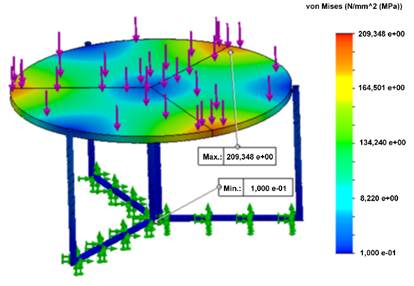
Figure 3 illustrates the Von Mises stress values obtained in the simulation, with a maximum recorded stress of 209 MPa. Fixed supports were positioned in the area where the structure contacts the ground and a load of 200 kg was applied, accounting for the simultaneous work of two individuals and the use of specific equipment or tools. A36 structural steel, with a minimum yield strength of 250 MPa and a tensile strength of 400 MPa, allows for an elongation of 20 % (Moreno-Pallares & Quinga-Morales, 2022). In this instance, the stress of 209 MPa falls below the minimum yield strength for A36 structural steel, indicating a positive outcome. This suggests that the material should be capable of withstanding the applied load without undergoing permanent deformations. Nevertheless, it is decisive to acknowledge that practical applications may introduce additional factors, including structural design, loads, environmental conditions, and other relevant considerations.
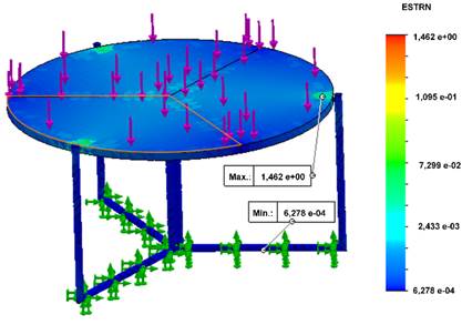
Unit strain serves as a metric for gauging the relative extension of a material under a load, often expressed as a percentage (Gutiérrez Rodríguez et al., 2021). In Figure 4, the data visualizes the values and locations of deformations occurring under the specified loading conditions, with a maximum recorded unit strain of 1.46 %. This unit strain value, when applied to A36 structural steel, is notably low and typically falls within the elastic limits of the material.
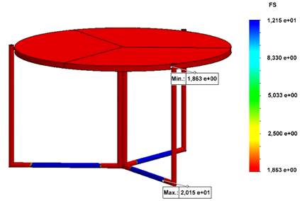
The factor of safety is a critical measure in engineering and design, ensuring that a component or structure can endure loads and service conditions without failure (Craig & Taleff, 2020). Figure 5 illustrates the factor of safety obtained through simulation, reaching a value of 1.84. This safety factor implies that the component is designed to withstand 1.84 times the maximum load it is expected to encounter when using A36 structural steel. Consequently, the design exceeds the strict necessities for fulfilling its function, offering an additional margin of safety. In the context of chair and table structures, a safety factor should have a minimum value of 1.69. Thus, a higher value indicates greater component strength, a crucial consideration in safety-critical applications.
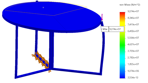
Under typical conditions, operators commonly work individually, with it being rare to see two people working together. Consequently, the load is defined as half the weight of a person, along with a load of objects and tools placed at one end of the table, totaling 50 and 25 kg, respectively, with a combined point load of 25 kg. Figure 6 displays the stress results obtained by applying these conditions to a structural support, reaching a value of 92.74 MPa, which does not exceed the yield limit, thus confirming the table's structural integrity.
Additionally, Figure 7a shows a maximum stress of 106.5 MPa when this point load is applied under the same conditions at the edge of the foldable section. Figure 7b illustrates how the table structure deforms, with a deflection of 1.27 mm, representing the most critical point of the cantilever structure. This indicates a design that will not fail under the specified conditions.
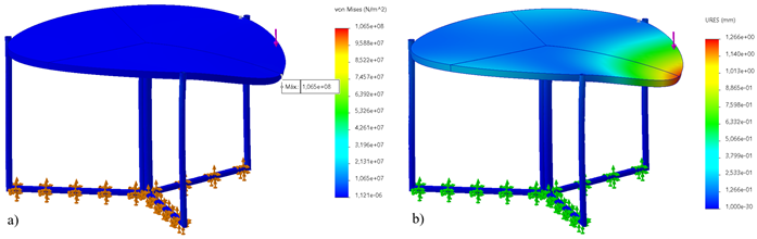
Figure 7: Analysis of applying a 75 kg point load on the table cantilever a) stresses, b) deformations.
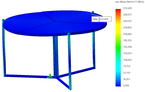
Furthermore, an alternative design of the table was analyzed using a different material for the supports. Aluminum was selected due to its density being approximately 2.5 times lower than that of structural steel. Figure 8 presents the results of applying a distributed load of 200 kg on the table surface with this modification in the material of the supports. The yield limit for the selected aluminum is 503 MPa, and with a maximum stress of 312.6 Mpa reached, a safety factor of 1.6 was obtained. By using aluminum for the supports, the mass was reduced to 38.57 kg, making it 14% lighter than with steel. However, the economic factor is significant, as costs increase with the acquisition of raw materials and the welding processes for the supports.
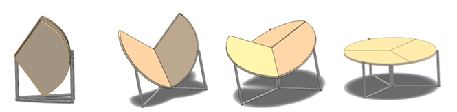
Conclusively, the study was augmented with the kinematic analysis of the table, verifying that the displacement of its components aligns with the specified trajectories. The calculation began with determining the angular velocity, averaging approximately 1 rad/s, under the premise that a relatively gentle motion should be maintained to prevent damage to the mechanism and ensure user safety. Additionally, the motion assumed constant acceleration, resulting in an angular acceleration of 0.1 rad/s². This factor accounted for the influence of gravity, stemming from the weight of the components, which could affect velocity but remained within the control of the user. Figure 9 illustrates the table design, showcasing its folded configuration for storage and its fully unfolded state for utilization.
Discussion
An essential aspect to consider, and the reason behind initiating the design, was the complexity of the folding mechanism. While the primary alternative for space optimization would be a rectangular table, its geometry proved challenging to divide into sections and ensure proper coupling for laying completely flat. Furthermore, more structural elements were needed, as it had to consist of at least four sections, thereby increasing the weight of the designated area. Equally crucial, design parameters focusing on ergonomics were taken into account, as explored by Ron et al. (2018), which analyzed height and usable area dimensions for a work table. This information is significant since poor posture during extended work periods is associated with various health issues and can also reduce work performance, as detailed in the study by Cercado-Bajaña et al. (2021). As outlined by Mínguez-García (2018) in their exploration of folding structures' impact on contemporary design, the significance of incorporating a folding table lies in the ease of maneuvering these mechanisms. With articulated joints linking the components, the structure gains flexibility, facilitating straightforward transportation and storage, akin to the compact nature of an umbrella when folded, yet providing substantial coverage when unfolded.
Furthermore, computer-aided design streamlines analysis via the finite element method, enabling both 2D and 3D modeling, alongside various static and dynamic simulations. The analytical approach and results presented in this study are juxtaposed with the methodology adopted by Calvo-López et al. (2022), who investigated loads and stresses on a CNC milling machine worktable. Additionally, to validate the derived values for the permissible stress of A36 structural steel, computational numerical analysis conducted by Páez-Redrován & Guerrero-Cuasapaz (2022) was referenced, yielding a relative error of approximately 7 %. Thus, the necessity of employing folding mechanisms and designing them using FEM is underscored, facilitating estimations closely aligned with reality and offering predictive insights into the structure's behavior under specified conditions.
Conclusions
The significance and benefits of folding structures are underscored through a synthesis of information gleaned from scholarly sources. While these structures facilitate efficient operation within confined spaces, a design capable of withstanding specific loads is imperative. For this study, a maximum load of 200 kg was chosen, factoring in the combined mass of two individuals and the essential tools typically used in a mechanical workshop. The design and modeling of the folding structure were executed using CAD software, resulting in a 3D model with 390 558 elements and 497 625. This included the distributed load and trajectory analysis definition, ultimately yielding a maximum stress value of 209.36 MPa, utilizing a 38.1 mm circular pipe section. Through load analysis, the utilization of a 38.1 mm (1 ½ in.) diameter round profile in A36 structural steel, with a yield stress of 400 MPa, was determined. A static simulation was conducted to derive results for the Von Mises stress and factor of safety. The design was validated as the Von Mises stress fell below the maximum steel stress, and a safety factor of 1.84 was obtained, confirming that the design withstood the established conditions. Lastly, the folding structure's design was validated through kinematic, mobility, and trajectory analyses, affirming its capability to be fully deployed for use and then retracted to reduce its space for storage.