INTRODUCTION
The existing problems of environmental changes worldwide have been derived from the consumption of fossil fuels, which is the main dominant in the energy matrix worldwide [1]. The elevated consumption has led to a rapid surge in the levels of carbon dioxide (CO2). This has led to a crisis of distribution, production, and consumption of energy, causing the scarcity of this fossil resource [2]. To mitigate the effects of environmental changes, the International Atomic Energy Agency (IAEA) and the Kyoto Protocol have proposed the use of renewable sources, which is accepted by developed countries [3]. This suggestion has spurred the development of fresh concepts involving the implementation of inventive prototypes aimed at alleviating the repercussions of high-consumer demand of fossil resources. [4].
Solar energy is the world's most abundant energy resource, provided by nature providing clean energy [5]. The photovoltaic cell converts solar energy into electricity through the use of doped semiconductors [6]. Extensive literature exists on the characterization of the cell or solar cell, as outlined below. The application of solar collectors has been evolving by proposing new models, such as Ion et al. [7] presented, a new flat plate thermal solar collector for the integration of facades. The numerical analysis considered a triangular geometry collector, modeling it in SolidWorks as design software and ANSYS to identify deformation and stagnation points. Three solar collectors with absorber plates in black, green, and orange hues were produced, yielding efficiencies of 55, 42, and 35 %, respectively.
The numerical and experimental investigation of a triangular storage collector was carried out by Ahmed [8]. As collectors are suitable devices for use in heating water, they are applied for domestic and industrial purposes. Andrade et al. [9] developed a systematic investigation for hours in the summer and winter seasons with and without a hot water outlet. Their experimental results showed that the efficiency during winter and summer at maximum temperatures was 48.7 % at 65 °C and 62.2 % at 70 °C, respectively. Moss et al. [10] affirm that collectors must be designed to be used in cold conditions, on cloudy days, or with high supply temperatures, to achieve maximum efficiency. The authors have deduced that the enhanced efficiency of solar collectors is attributed to the decrease in internal pressure, necessitating values below 0.5 Pa.
When comparing the efficiency of a solar collector based on ANSYS Fluent results with experimental data, it becomes evident that the inflow into the storage collector should occur at the bottom of the coldest section. Simultaneously, the outflow from the storage collector should be positioned at the top of the collector's coldest section [11]. By considering the literature review carried out and that has been taken as a reference, for the development of this investigation, Table 1 presents a brief description of the most relevant publications, which used a flat-plate solar collector.
Table 1: Investigations carried out on flat collectors
| Parameter | Efficiency [%] | Water as the working fluid | Coating | Max. Temp. [°C] |
|---|---|---|---|---|
| Ion et al. [7] | 55 | X | X | 80 |
| Ahmed [8] | 62.2 | |||
| Moss et al. [10] | X | |||
| Fathabadi [12] | 74.9 | X | ||
| Saffarian et al. [13] | X | |||
| Müller et al. [14] | X | X | 16.5 | |
| Fan et al. [15] | 69.4 | X |
The aim of this work is the geometric comparison between triangular and square solar collectors. For this, the obtained data, the efficiencies, and the maximum temperatures were contrasted, which can be reached with the constant solar irradiation flow of 1 000 W·m-2. This document is organized as described below, Materials and Methods present the parameters of each collector, as well as the mathematical modeling necessary to support the investigation. In Results, the obtained graphs for each geometry with the simulation software are compared. Finally, in the Conclusions, the obtained results are discussed and the presented information is summarized.
MATERIALS AND METHODS
Conceptualization of the design
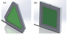
Solar collectors are mechanisms used to gather, impregnate, and transfer solar energy to a fluid, which can be water or air. They can also be utilized to heat water, for heating systems, or heating swimming pools [16]. Among the types of renewable energy, solar is very prominent, due to the use of photovoltaic cells and collectors to produce electricity and water heating, respectively, in industrial processes or integrated systems of homes [17]. Solar collectors are used for various applications and different utilities, trying to take better advantage of the use of solar energy. Therefore, a different geometry of a solar collector is proposed, considering the design presented by Ion et al. [7]. Fig. 1a shows a triangular solar collector, to compare the efficiencies against a square collector, as shown in Fig. 1b.
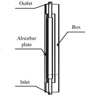
The central body consists of an aluminum cavity that will be located under the absorbent plate of the collector through which water, as working fluid, will circulate. Fig. 2 shows the cross-section used for both geometrics, where the absorber plate contained in a box is displayed.
The central body consists of an aluminum cavity that will be located under the absorbent plate of the collector through which water, as working fluid, will circulate. Being made of corrosion-resistant aluminum material, it will allow hot water to be used for any need that the user requires. When used for the facades of buildings or houses, coatings must be placed to obtain an architectural design. For the joining and sealing elements, rubber is applied between the aluminum cavities and the absorbent plate [18]. The design needs to use not very thick absorber plates to take advantage of the heat transfer to the fluid since thick plates absorb a lot of heat and not all of this heat is transferred to the fluid [19].
Solar thermal collector model
The triangular and square collector models were designed in SolidWorks, resembling the measurements in the article by Ion et al. [7]. The simulation was carried out in ANSYS Fluent, in which, the input conditions are presented in Table 2.
Table 2: Parameters utilized in the simulation
| Parameter | Symbol | Units | Value |
|---|---|---|---|
| Tilt angle | β | - | 0 |
| Ambient temperature | T a | °C | 20 |
| Absorber plate thermal conductivity | k | W·m-1·K-1 | 237 |
| Specific flow rate | mkg·m-1·s-1 | 0.02 | |
| Absorber plate emissivity | ε p | - | 0.115 |
| Absorber plate temperature | T p | °C | 20 - 100 |
| Solar irradiation | G | W·m-2 | 1000 |
For the design of the collectors, both triangular and square, only the geometry sketch was considered. It allows to parameterize the simulation and obtain the required results. The velocity was determined in relation to a specific flow rate of 0.02 kg·m-2·s-1 and irradiance ranging from 800 to 900 W·m-2 [7]. Under these conditions, there is a favorable trend towards elevating the temperature from 20 °C to approximately 60 °C.
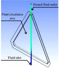
In Fig. 3, the schematic of the triangular solar collector is depicted, with the water inlet marked in blue at a temperature of 20 °C. The central section of the collector corresponds to the region where the working fluid will circulate. At the top, there is the outlet of the working fluid that has been heated. The proposed square solar collector also complies with the same schematic characteristics as the triangular solar collector.
Table 3 details the parameters that both triangular and square solar collectors share, with similar characteristics.
Mathematical modeling of the flat-plate solar collector
In flat-plate solar collectors, regardless of geometry, the amount of solar radiation absorbed by the collector is an important factor [12]. The received solar heat (Q in ) for a flat plate collector is expressed with equation (1):
Where Ac is the collector area and G is the solar irradiation. Equation (2) is employed to calculate the useful heat (Q u ) within the solar collector, considering the circulation of the working fluid within the collector, as detailed by Diez et al. [20]:
Where 𝑚 is the mass Flow rate, c p is the specific heat for water, T out and T in are the water temperature at the inlet and outlet, respectively. The global coefficient of heat loss (U L ) is a variable taken into account during the design phase of solar collectors. Anca et al. [21] have used equation (3), which expresses the sum of the loss coefficients:
The higher loss coefficient (U t ) is obtained in the glazing due to the convection of heat and radiation that takes place in the absorber plate and as the radiation loss from the external glass plate to the environment. Wang et al. [22] use equation (4):
The convective heat coefficient (h c,p-c ) from the cover glass and absorber plate can be calculated by Deshmukh et al. [23] from equation (5):
Where L is the characteristic length and k is the thermal conductivity of the material. The Nusselt number (N u ) can be determined based on the Rayleigh number and the inclination angle, ranging from 0 to 75° taking into account its operation in a natural convection [24], through the application of equation (6):
Where β is the Coefficient of thermal expansion. The Rayleigh number (R a ) is calculated by Robles-Campos et al. [25] by applying equation (7):
Where g is gravity. The radiation coefficient from the absorber plate to the cover (h c,p-c ) is derived using the equation (8):
Where ε is the emissivity. For the calculation of the radiation coefficient of the outer cover (h r,p-c ), Gunjo et al. [26] applied equation (9):
The background loss coefficient caused by heat conduction (U b ) is calculated with equation (10):
Mustafa et al. [27] calculated the border loss coefficient (U ε ) due to heat conduction by using equation (11):
To obtain the efficiency of the collectors, the following relationships are applied [28]. Equation (12) allows to obtain the thermal power ( 𝑄 ) of heat output from the collector, which is expressed as follows:
Finally, the relation of the equation (13) has been used by Xu et al. [29] for the direct calculation of the efficiency of the solar collector:
ANSYS Software Equations
Energy
Quitiaquez et al. [30] conceptualize that the most important and powerful scientific laws are the conservation laws, in which, energy is a constant that is conserved in the universe. Therefore, it is declared that energy is neither created nor destroyed, it is only transformed. Equation (14) expresses the energy conversation equation to carry out a steady-state thermal analysis [31]:
Energy Radiation
Solar energy represents an essentially limitless source of power, serving as a foundation for the creation of projects centered around this renewable alternative. This type of analysis considers radiative heat transfer, which is the transfer of thermal energy via electromagnetic waves. Mohamad et al. [32] articulated the representation of solar radiation in equation (15):
Where 𝑟 and 𝑠 representes the position and direction vectors, a and σ s are the absorption scattering coefficients, respectively. I is the solar intensity, n is the refractive index, T is the ambient temperature and Ω is the solid angle. And for heat transfer by radiation, the Stefan-Botlzmann constant (σ) is 5.669 x 10⁻⁸ W·m-2·K-4.
Meshing
The finite element method allows the structural model to be perfected, creating an iteration process by applying a level of precision that ensures adequate convergence of the process. If the guarantee of this process is not adequate, the quality of the results in the analysis of the design will be poor, granting a convergence of the non-optimal solution [33].
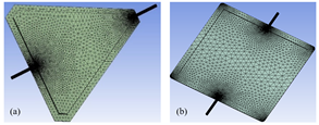
The mesh metric presents the information of nodes and elements, hence, the selection of a good mesh quality provides a better accuracy in the convergence of the solution in the simulation. For an excellent mesh, it is found in the values of 0 to 0.25 and for a lousy mesh surrounds the range of 0.98 to 1.00 [34]. Based on the aforementioned parameters and selecting a method of dominant tetrahedra, the metric of the triangular and square solar collector designs is performed by a selection of the mesh that is approximately in a range of 0.2486. Fig. 4a and Fig. 4b presents the discretization for the triangular and square collectors, respectively.
RESULTS
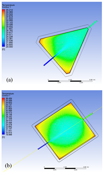
Fig. 5a and Fig. 5b present the temperature contours, therefore, it is possible to predict the behavior that the collectors will have throughout the increase in the flow of solar irradiation. The fluid initiates with an inlet temperature of approximately 20 °C, and the outlet temperature is monitored as the fluid exits the collectors.
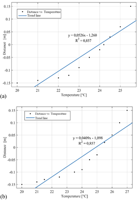
In Fig. 6a, the temperature trend graph of the working fluid originates at 20 °C, tracing the path of the triangular collector until it reaches an outlet temperature of 25.5 °C. Similarly, in the square solar collector illustrated in Fig. 6b, the identical trend line is apparent, albeit with the distinction that the working fluid's outlet temperature is 27 °C. Consequently, when compared to the temperature of the triangular collector, a notable difference is evident between the two geometries.
The trend lines illustrate a proportional relationship between temperature and distance. Consequently, the forecast includes the maximum temperature that the working fluid is anticipated to reach based on the solar irradiation flux and the heat transfer area of each collector. The linear correlation coefficient R² serves as an indicator of the model's fit [35] and in the simulation, the obtained data exhibits a value of 85 %, signifying the proportion of variability in temperature increase relative to the distance covered by the working fluid. This figure suggests a reasonably acceptable reliability in the correlation between the data.
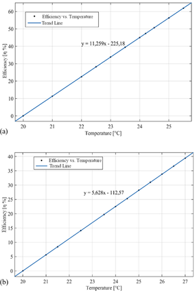
The calculation of the efficiency, equations (13) and (14) are applied, in which the thermal power of the collectors is calculated. It describes a tendency of the efficiency as a function of the temperature. Fig. 7a illustrates the performance of the triangular collector, depicting the efficiency trend. The highest efficiency is achieved at a maximum temperature of 62 %, occurring at 25.5 °C. The square collector had an efficiency of 39 % at 27 °C and a cause for this very high variation in efficiency and temperature could be due to the geometry of each collector, as shown in Fig. 7b. The heat transfer areas of the absorber plate of both the square collector and the triangular collector are wider.
The designs put forth in this research were developed by considering the geometry of an actual rectangular solar collector, which served as the basis for subsequent modifications. Moldovan et al. [36] conducted CFD simulations aimed at optimizing the efficiency of a triangular solar collector, taking layer thickness into account. They achieved an average efficiency of 55 %, and with a mass flow of 0.01 kg·s-1 and a 5 mm thickness, the maximum efficiency reached 66.12 %. Similarly, Noghrehabadi et al. [37] explored the efficiency of a square solar collector using both water and a nanofluid with silicon oxide as working fluids. The incorporation of nanofluid significantly enhanced the collector's efficiency, exceeding 50 %, while the use of water resulted in efficiency variations between 30 and 50 %, considering variations in mass flow and incident solar radiation. The efficiency outcomes for the proposed geometries align with those found in the literature, validating their credibility. However, further investigation is warranted to optimize the design, taking into consideration a more in-depth analysis of other variables associated with efficiency.
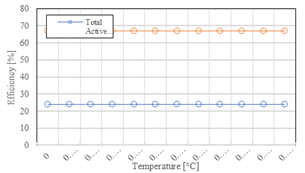
Fig. 8 presents the comparison of the efficiencies between both solar collectors that start from the same temperature of 20 °C. The efficiency of the solar collectors changes as the temperature increases, reaching a great difference in efficiency of 23 % between the collectors. The efficiency of the triangular solar collector closely mirrors the efficiency of the model introduced by Ion et al. [7], the first one to propose a collector with these characteristics. A triangular solar collector may potentially exhibit higher efficiency owing to its capacity to capture solar radiation from broader angles throughout the day, particularly at varying latitudes. Moreover, the triangular geometry can provide a larger surface area for absorption in a specific orientation when compared to a square collector. Comprehensive evaluations through computational simulations and experimental tests are essential to assess and compare the efficiency of various solar collector geometries in specific contexts.
CONCLUSIONS
The efficiency comparison of the triangular and square solar collectors was analyzed. Modeling was designed in SolidWorks and simulations were carried out in ANSYS Fluent, obtaining a mesh skewness of 0.2486. The triangular collector demonstrates notable efficiency in converting solar radiation into usable heat, with 62 % of the incident radiation being effectively converted into thermal energy. In contrast, the square solar collector exhibits a lower efficiency, signifying a less effective conversion of only 39% of the incident solar radiation into thermal energy. Temperature reaches maximum values for square and triangular solar collectors of 27 and 25.5 °C, respectively. The material utilized for the design of the solar collectors is aluminum which has a high thermal conductivity. Finally, the collector behavior was analyzed with a color scale figure, which shows that higher temperatures tend to concentrate in the corners of the collectors. Therefore, a certain amount of heat will be discarded and for this reason, it is not possible to have higher levels of efficiency. Attaining an optimal design that maximizes the capture of solar radiation while minimizing thermal losses can pose challenges, and the process of optimization frequently demands a thorough, application-specific strategy.


