


 Español (pdf)
 Articulo en XML
 Referencias del artículo
 Enviar articulo por email
 Citado por SciELO
  Similares en
SciELO
Similares en
SciELO 
 Permalink
1. INTRODUCTION
Several machines that compound diverse manufacturing processes are actuated by three-phase alternating current (AC) induction motors because of its simplicity, robustness and cost, therefore, controlling its operation is a highly relevant task in industry (Dukare and Jagtap, 2017). Another relevant technology for industrial processes is the programmable logic controller (PLC), whose reliability, operation simplicity, electrical and mechanical robustness and high speed turn it into the preferred device in industry for the execution of automation and control algorithms (Dukare and Jagtap, 2017). Additionally, the possibility of developing PLC networks that might include other industrial-purpose hardware, such as human-machine interfaces (HMI), increases the aforesaid preference of PLC and stand out their versatility. For such a reason, several manufacturing companies in Mexico are reluctant to the use of computers, embedded systems or laboratory-purpose hardware and software to automate or control their machinery, even though these devices might execute cutting-edge automation and control algorithms that could be beneficial to optimize or improve industrial processes.
Considering the aforementioned problem, an appropriate alternative for the industry could be the implementation of automation and control algorithms using just industrial-purpose hardware. In this context, and recalling the idea of the wide usage of three-phase AC motors, several researchers have reported PLC-based control systems for such electrical machines (Verma and Potdar, 2017) in the literature. One of the most remarkable results was presented by Saad and Arrofiq (2012), in which the authors programmed a fuzzy controller for an AC motor within the PLC, but they used a laboratory-type sensor, namely a DC motor adapted to work as a generator. Similarly, Howimanporn et al. (2016) reported an optimized PID controller for a conveyor belt actuated by an AC motor, nonetheless, the authors also used laboratory-purpose hardware to send the control signals to the motor. Some examples of the usage of laboratory-purpose software can be found in the works of Al-Manfi (2019) and Awdaa et al. (2020); in both cases the closed-loop control for the motor is implemented by means of high-cost software executed on a personal computer (PC) in addition to the PLC.
On the other hand, some works that only use industrial hardware have been reported as well, for instance, the speed control of a three-phase motor for a centrifugal machine of a sugar manufacturing process was reported by Pramudijanto et al. (2015). The authors implemented a predictive PID controller on a PLC, however, they do not specify the technology used for feedback, the execution of the control algorithm is not explained and their results are not clearly presented in plots, but only a 10.79 root median squared error (RMSE) is presented. In addition, Mahesh and Ramachandra (2017) presented a PLC-based P controller using just industrial-purpose hardware, obtaining successful results with an average of 2 % steady-state error. Nevertheless, the authors do not show plots of the behavior of the speed and they do not present theoretical foundations. Another PLC based closed-loop controller without laboratory-purpose hardware is reported in the work of Demir et al. (2019), achieving a zero steady-state error in 40 seconds for their largest step reference from 0 to 1000 [RPM]. Despite these successful results, it is worth mentioning that the authors did not program the control algorithm but they only implemented and configured the proportional-integral-derivative (PID) controller functional block of the PLC programming environment. This represents a limitation if it is pretended to implement more advanced control techniques.
Besides, some researchers have tried to exploit the versatility of the PLC networks to control the speed of AC motors. For example, the use of open-platform communications (OPC) servers using Ethernet and other field buses to connect the PLC with variable-frequency drives (VFD) were presented by Velagic et al. (2011) and Al-Manfi (2019), in order to implement PID controllers. However, the use of a non-industrial-purpose PC within industrial environments is still a drawback for such approaches since the robustness of the system might be compromised. Recently, a very interesting fully industrial setup for induction motors control was reported by Vadi et al. (2022), these authors use a PLC Profibus network to communicate the PLC with the VDF, but the closed-loop control action is still missing.
Considering the information found in the literature, the problem of implementing closed-loop control systems using just industrial- purpose hardware is not fully overcome. In this context, the contribution of this paper is twofold: in one hand, up to the best authors’ knowledge, this is the first time that a PI controller is analyzed, clearly explained and fully programmed within a PLC using an industrial encoder as feedback. This represents a step towards the implementation of more complex control systems on industrial devices. On the other hand, the control system uses a Modbus network in order to communicate the feedback-analyzing PLC with the control PLC, the VFD and also an HMI that is useful to command the target speed and also to monitor the measured velocity. In order to assess the correct operation and the robustness of the full setup, the following experiments were put into effect: firstly, the controller was commanded with large target velocities to prove its stability in the whole error space; later on, the importance of the integral action is evaluated and highlighted through the disturbance rejection capability assessment. The successful results demonstrated that the proposed control architecture is suitable to effectively control three-phase AC motors by means of only industrial hardware, eliminating the necessity of high-cost additional software or laboratory-purpose hardware that is more likely to fail in industrial environments. Furthermore, the developed control algorithm yielded better results than those reported in the literature in terms of time of response and quantitative performance indices. Finally, the implementation of a Modbus network stands out the versatility of the industrial hardware and opens the possibility of involving more devices and adding functionalities depending on the application requirements.
The organization of this paper is as follows: firstly, the used methods are described in Section 2, namely the industrial hardware network is described in addition to the mathematical model of the plant as well as the control system design and its implementation. Then, the Section 3 addresses the experiments carried out and the obtained results are discussed and contrasted against the state of the art. Finally, the Section 4 concludes the paper.
2. METHODOLOGY
Below, the full system setup used for this research is described, as well as the development and implementation of the proposed control technique using the industrial hardware network.
2.1 System Description
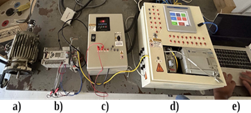
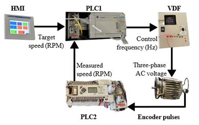
The implemented experimental system is displayed in Figure 1. It is composed of two control and power panels, respectively, as well as an independent station dedicated for the speed data acquisition from the three-phase AC motor. The first panel is integrated by a Micrologix 1500 PLC (hereinafter PLC1) and a HMI Panel View Plus 600 touch screen. Furthermore, the 1761-NET-ENI and 1761-NET-AIC modules have been adapted to the PLC1 to communicate it with other devices through the Ethernet and RS845 communication standards, respectively. The second panel contains a PowerFlex 40 VFD that feeds the AC motor with three-phase 220 [VAC]. Such a motor demands a 0.5 [HP] power, and its nominal speed is 1,800 [RPM], moreover, it is equipped with a 600-pulses-per-revolution quadrature encoder attached to the shaft.
Firstly, it was tried to implement the whole control system in the PLC1, however, the encoder counting and the control system algo- rithms execution interfered with each other affecting the correct control operation. Thus, it was decided to implement a Micrologix 1400 PLC (hereinafter PLC2), to which a 1761-NET-AIC module was also incorporated. This PLC was chosen since six of its digital inputs are capable to operate as high-speed counters (HSC), namely up to 100 [kHz], which turns this PLC into the most competitive model within the Micrologix PLC family in this regard, however, the same problem of interfering algorithms arose while executing the whole control system in the PLC2. In order to solve such a problem, it was decided to implement a dedicated station to capture and process the encoder signal for its later transmission and usage.
The reference data for the implemented speed control system, in [RPM], is entered by the user through a graphical interface embedded into the HMI screen. In the same interface, the speed data of the motor shaft is displayed also in [RPM] after having been conditioned by the Micrologix 1400 PLC (hereinafter PLC2). Likewise, the magnitude of the error and the control signal sent to the VFD, both in [Hz], are displayed in two other labels. Some buttons to perform the functions of start, stop and reverse rotation are included as well to manipulate the AC motor.
The communication between the devices in charge of both the acquisition of the feedback signal, as well as sending the control signal, is carried out through the Modbus protocol, supported by the 1761-NET-AIC module and by the VFD itself, through an RS485 input provided. Meanwhile, for the interaction between the HMI screen and the Micrologix 1500 PLC, the Ethernet IP protocol is used, associated with the 1761-NET-ENI module.
Based on its interaction with all the elements of the implemented control system, the corresponding control algorithm is executed in the PLC1. In this case, a discrete Proportional Integral (PI) controller. It is worth mentioning that the code developed, built on the IEC-61131-3 programming standard (ladder language), does not use any specialized function for the application of the mentioned PI controller, but the algorithm was completely developed from scratch using a numerical integration.
2.2 Plant Modelling
In order to obtain a transfer function that relates the three-phase motor speed with the VDF frequency, the well-known Ziegler-Nichols reaction curve method was implemented.
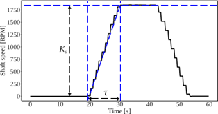
According to the parameters obtained from the Ziegler-Nichols reaction curve method, as shown in Figure 2, the transfer function representing the relation between the shaft speed of the three-phase AC motor with respect to the frequency input is given by
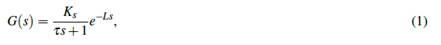
in this case, K s = 1, 800 and τ = 11 and L = 0. It is worth mentioning that this modelling approach, besides its wide use in industry, is well supported in the literature for its use in electrical motors (Ustun and Demirtas, 2009; Bhatti et al., 2016; Avdeev and Vyngra, 2020; Nicola and Nicola, 2021).
In order to adequately synchronize the Modbus network, a sampling period of 250 [ms] was implemented. Thus, a discretization of the system (1) was put into effect based on the aforementioned period and the zero-order hold method and resulting in the discrete-time transfer function
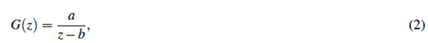
with a = 40.45 and b = 0.9775 according to the discretization process. Now this transfer function is helpful to design a discrete-time
closed-loop control system.
2.3 Control System Design
The control target in this work is to lead the shaft speed of the AC motor ω (k) to a desired value ωd (k), with k ≥ 0 denoting the sample number. In this context, a feedback controller is required to reduce to zero the error between the desired speed and the measured speed, namely, e(k) = ωd (k) − ω (k). Since (2) is a first-order system without delay, a Proportional-Integral (PI) controller is suitable to regulate the shaft speed (Landau and Zito, 2010), therefore, considering the error in the Z domain, E(z) = Ωd (z) − Ω(z), the transfer function of the mentioned controller is (Moudgalya, 2007):
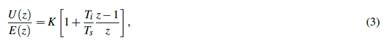
where K > 0 is the proportional gain to be defined, T i > 0 is the integral time and T s is the sampling period. Even though the control parameters can be determined using the Ziegler-Nichols approach, the system delay is zero and hence, such a methodology is not applicable. Besides, the gain tuning procedure was conducted by analyzing the pole of the closed-loop transfer function with only the proportional controller, which is given by
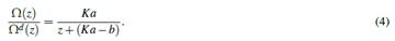
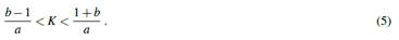
Considering the stability condition, −1 < z < 1 (Ogata, 2015), the proportional gain can be computed with
Once the stability is ensured with the proportional controller, the integral action was added yielding the following closed-loop transfer function (Landau and Zito, 2010)
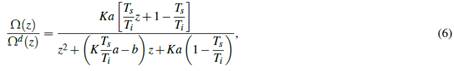
where T i is the integration time. In this work K = 0.01 was selected, which satisfies the stability criterion for the P controller. In addition, the integration time was determined considering a period of 25 [ms] to allow a correct pulse count from the encoder, therefore, the ratio T s /Ti must be 0.025 and consequently, the integration time was computed as 20 [s]. Finally, the stability of the closed-loop system with PI controller (6) is guaranteed since both poles z 1,2 = 0.4728 ± 0.7526 j are inside the unit circle of the complex plane.
2.4 Controller Implementation
The controller (3) in terms of equations of differences can be expressed as (Bolton, 2021)
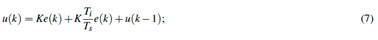
this last expression was programmed in the PLC1, using the ladder language within the RsLogix programming environment. In order to compute the control signal u(k), the error was firstly computed by means of both the target speed ωd (k) and the shaft speed ω (k). The first one can be directly commanded through the HMI touch panel with a range from 0 to 1,800 [RPM] and later on is sent to the PLC1 using the Modbus network. The latter is obtained from the encoder attached to the shaft of the AC motor; the generated pulses are counted at a 20 [kHz] frequency with the PLC2 and later transferred to the PLC1 also through the Modbus network; the use of the PLC2 is justified since only this device was capable to accurately read the encoder pulses while spinning at the nominal shaft speed. Next, the PLC1 computes the control signal u(k), as it was mentioned before, and transforms it into frequency units with a range from 0 to 600, which is also sent via the Modbus network to the VFD. Finally, such a signal is translated to the range from 0.0 to
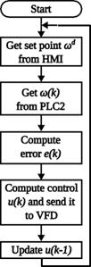
60.0 [Hz] and then applied to the AC motor. The block diagram of the full control system is depicted in Figure 3, where all the signals and the devices processing them are illustrated. In addition, the flow diagram of the control system algorithm executed by the PLC1 is shown in Figure 4, where the interaction between the PLC and other devices can be observed meanwhile it executes the proposed control system.
3. Experiments and Results Discussion
In order to evaluate the correct operation and robustness of the proposed Modbus control network, some experiments were performed. The details of their conduction and the results are detailed below. A video of the experiments can be found at https://youtu.be/ zDgAH1HhDGA.
3.1 PI Controller using Large Step References
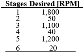
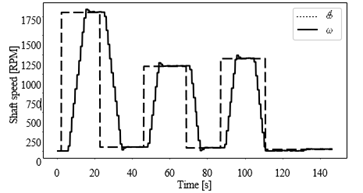
Once the PI controller algorithm was programmed within the PLC, the first test to evaluate the performance of the implemented system consisted in widely changing the set-point speed. In this way, starting from a total inactivity state of the motor (0 [RPM]), the maximum admissible speed value was commanded, namely 1,800 [RPM]. After the motor speed converges to the commanded value, the set-point was shifted to 50 [RPM]. This process was repeated by commanding diverse large steps as the assigned reference values, which are displayed in Table 1. Likewise, it is possible to appreciate the graphic behavior of such changes in Figure 5, and how the response is established in the assigned value for each case analyzed, nullifying in all cases the steady-state error and yielding an overshoot of less than 2 %.
3.2 Disturbances Rejection Assessment
After validating the proper behavior of the PI controller while facing sudden changes in the speed reference value, some other experiments were carried out to visualize and compare the responses obtained using both the PI controller and a proportional (P) controller,
after applying a disturbance torque to the AC motor shaft. The main target of this experiment is to evaluate whether the proposed controller would recover the set-point speed of the motor shaft, despite the presence of disturbances, such as the application of load on the shaft for instance.
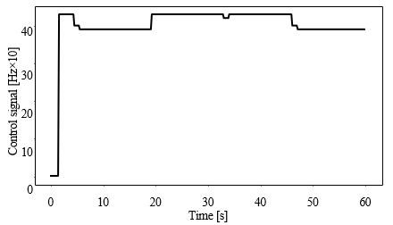
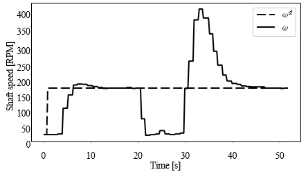
Fort the case of the P controller, as shown in Figure 6, it can be seen how the speed drops from 120 [RPM] to almost zero after applying a disturbance. The controller is unable to set an output that can effectively cope with the effect of the load. On the contrary, it seems that the control signal is similar with or without the presence of disturbances as can be seen in Figure 7. Therefore, this control action alone is insufficient to keep the shaft speed at the desired value in presence of disturbances.
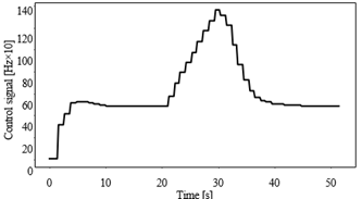
Regarding the action of the PI controller, in Figure 8 it can be seen how eventually, after the shaft speed drops due to the action of the imposed load, the controller computes and supplies a larger amount of energy leading to maintain the magnitude of the speed at the entered target value. Likewise, in Figure 9 it is observed how after having established a considerable energy to mitigate the load effect, the speed is again regulated to its given set point.
In order to provide a quantitative result to show which performance is better among both controllers (Balestrino et al., 2006), the Integral of the Absolute Error (IAE) and the Integral of the Absolute value multiplied by Time of the Error (ITAE) were computed as follows
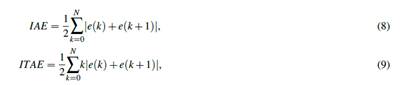
where N is the number of samples of the experiment. The resulting values are listed in Table 2, where it can be observed that the PI controller significantly reduces both indices.
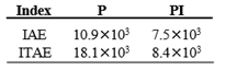
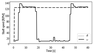
Figure 6 Time evolution of the controlled shaft speed with P control and application of disturbances
3.3 Results Discussion
Figure 5 shows that the proposed PI controller (7) executed by the Modbus network devices is effective for speed- regulation despite how large the set points from each other are. No steady-state error and a 2 % overshoot can be also appreciated which is acceptable for this industrial machine. The importance of including an integral action to improve the robustness of a control system is stood out from the disturbance rejection assessment. Figure 8 shows how the speed is recovered after a disturbance using the PI controller (7) in contrast to Figure 6, where it can be observed that the shaft remained steady during the disturbance application when using the control P (4). Likewise, Figure 9 shows that the PI control signal increased while the disturbance was being applied, in contrast to the P control signal in Figure 7, where no significant change can be appreciated, resulting in insufficient energy to mitigate the disturbance action. The computed indices (8) and (9) shown in Table 2 are consistent with the graphical results, showing that the PI controller reduced the error caused by the applied disturbance.
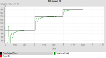
Moreover, the obtained results in this work were contrasted against those obtained by Pramudijanto et al. (2015) and Demir et al. (2019), since these are the only similar works presenting their results. For the case of the predictive PID controller reported by Pramudijanto et al. (2015), the RMSE was computed using
resulting on a value of 10.79 for similar-to-step references. In this work, the RMSE was computing with (10) as well resulting on a value of 8.41 for larger true-step references, which is 22 % less than the RMSE reported by Pramudijanto et al. (2015). Now considering Demir et al. (2019), it is worth remembering that the authors used the PID functional block available in their programming environment, meanwhile in this work, the full control algorithm was developed from scratch. Figure 10 shows the speed regulation plots obtained by Demir et al. (2019), where it can be observed that the AC motor speed reached the steady state at the desired value after 40 seconds from 0 to 1000 [RPM]. In contrast in this work, the steady state at the desired value was achieved in 18 seconds from 0 to 1750 [RPM]. Hence, the results presented in this work overcome those obtained by Demir et al. (2019) in terms of faster response for larger errors, namely, the proposed controller reduces 12 seconds the set point steady state accomplishment for a 75 % larger error.
4. Conclusions
In this work, the implementation of a closed-loop controller to regulate the shaft speed of a three-phase AC motor was presented. Such an implementation was performed using only industrial-purpose hardware, which is an advantage over the state-of-the-art approaches so far, in addition to the completely novel use of a Modbus network to perform a digital control system for an AC motor. The control system technique used was a PI controller, whose performance and robustness were evaluated by way of the following experiments:
1) commanding large set-points to the PI controller to verify its effectiveness throughout the whole error signal span; 2) comparing whether or not using the integral action in order to highlight its necessity for disturbance rejection.
From the first experiment, the results are considered successful since the controller is capable to lead the shaft speed to a desired value despite how far from the current condition is; besides, the steady state error is practically nullified.
For the case of the disturbance rejection assessment, it can be seen that the integral action works correctly, since the control signal increased to mitigate the effects of the disturbance and it reduced the IAE and ITAE performance indices as well. This leads to the conclusion that the integral action would be helpful to maintain the commanded speed despite the presence of a constant load on the shaft, for instance, using the AC motor to actuate a conveyor belt or to move another type of machine.
Finally, the obtained results from speed regulation can be considered superior with respect to the state of the art since the RMSE value at steady-state error was reduced 22 % with respect to the results presented by Pramudijanto et al. (2015) and the steady state at the desired set point was accomplished 12 seconds earlier than the controller presented by Demir et al. (2019) for a 75 % larger error.
From the successful results of these experiments, a correct operation and performance of the Modbus network can be concluded as well. All the set of these promising results encourages the use of only industrial-purpose networked hardware to implement more complex control systems rather than traditional high-cost academic-purpose hardware and software, which are less interesting for manufacturing industry in Mexico.