1. Introduction
The World Health Organization data estimate that around one billion people of the world's population live with some type of disability, amount that represents about 15 % of this. The displacement disability is one of the most frequent worldwide that hinders the activities of daily life of the sufferer. The most common pathologies that happens in the lower limbs are fractures, arthrosis and venous insufficiency and can occur due to factors such as traffic accidents, sports injuries, aging, degenerative diseases and lifestyle (OMS,2011).
An alternative for motor recovery is to include the patient in a rehabilitation program implemented by the physiotherapist, in order to prepare the musculoskeletal system to have a better performance in an active job. Studies mention that rehab therapies complemented with robotic systems help shorten the recovery time and maximize the performance of the affected body area (Brosseau et al.,2004).
With technological development and engineering, various devices have been designed that provide a routine of comprehensive training to the patient. Among these are the systems of a degree of freedom, as the work proposed by E.E. Rosero (Rosero et al., 2011) for the rehabilitation of the knee, through a rocker-rod-slider mechanism, and the system proposed by C. H. Guzman (Guzmán Valdivia et al., 2014) for the rehabilitation of the ankle through an actuated slide (mobile slide). Both mechanisms are an alternative rehabilitation in the home, for factors such as cost and portability but they are limited to perform simple training routines such as flexion and extension of a specific area.
In order to grant training routines that prepare the affected limb to a better active work, mechanisms of a degree of freedom that simulate the movement of the limb have been developed, like the 4-link mechanism of Z. Ji (Ji and Manna, 2008) the mechanisms of 6 and 10 links proposed by B. Y. Tsuge (Tsuge et al., 2016) (Tsuge and McCarthy, 2015) and the mechanism Stephenson III of Y. Shao (Shao et al., 2016). It is important to mention that for the design of these systems only the dimensional synthesis for an objective trajectory is considered.
From a viewpoint of mechatronic design, for a mechanical design is not enough to focus on the synthesis dimensional, but it is necessary to consider the existing commitments between the mechanical system and the control system, since if both factors of form are taken into account concurrent it is possible to obtain a mechanical structure that facilitates control (Li et al., 2001).
This paper presents the structural design of a mechanism of rehabilitation of a degree of freedom for lower limbs, considering as a conceptual model 8-link mechanisms (Pantoja-García et al., 2017). To obtain the mechanical structure, an optimization problem is posed in which the dimensional synthesis for a desired trajectory and the minimization of torque are established as objectives, being the latter the factor that allows obtaining a mechanical structure that facilitates control.
2. Conceptual design
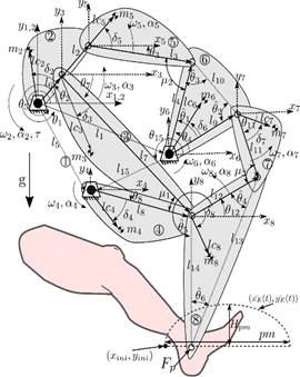
For the design of the rehabilitation mechanism, the 8-link mechanism is considered as a conceptual model of the Figure 1, which is made up of 7 mobile links (links  ) and a base or bancada link (link 1). Between the mobile links there are four binary links
  and two ternary links
  .
.
The point  is established as the support area of the patient's ankle and is the place where a rehabilitation trajectory is executed.
3. Formulation of the optimization problem
For the design of the rehab mechanism, a concurrent design is considered in which it is planned to meet two objectives, the dimensional synthesis to generate a trajectory in the point  and minimize the torque of the mechanism.
Because it is required to satisfy both requirements simultaneously, an optimization problem is posed through the weighted sums approach as shown in Equation 1. Where  represents the path error,
  represents the mechanism torque,
  is the weight attributed to the trajectory error,
 is the weight attributed to the torque,
  is the vector of design variables,
  and
and  are the lower and upper limits of the design variables,
  are the inequality constraints necessary to guarantee the functionality of the mechanism, and
  and
and  represent the constraints of kinematics and dynamics of the mechanism.
This is subject to:
The path error  is defined by the Equation 2, which describes the difference between the desired path expressed in the coordinates
  and the path of the point
  defined by the coordinates
4. Design variables
As design variables, the kinematic parameters of the mechanism determined by the position vectors  , the internal angles of the ternary links
  and
and  , the angles of the base links
  and
and  , the angular displacements of the crank
  and the initial coordinates of the desired path
  and
and  were considered.
The dynamic design variables are determined by the design parameters of the links  (Figure 2)
 . Where the parameter
  is determined by the position vectors
  .
.
Therefore the vector of design variables  for the optimization problem is presented in Equation 3, and it has a dimension of
  elements, where
  represents the number of crank angles
  required to generate the desired path.
It is important to note that  is defined discretely as described in the Equation 4, where
  represents the final time of evaluation for
  .
.
5. Constraints
For this optimization problem it is necessary to establish constraints that guarantee the functionality of the mechanism, therefore a set of mechanical constraints are established which are described below:
5.1. Path
The proposed rehabilitation path is a semi-elliptical curve defined as shown in Figure 4(a). The equations that define this path depending on the temporal and spatial biomechanical parameters of a person presented in Equations 5 and 6. Where we have as temporary parameters, the time in the phase of support  the time in the swing phase
 , the sample rate of the signal
 , and the total time of a march cycle
  which is defined as
  . As spatial parameters we have, the step length
  , the height of the step
  and the starting point of the path defined by the point
  .
.
5.2. System kinematics
The kinematics of the system is a constraint that governs the behavior of the mechanism and through this it is possible to know the path of the point  .
.
To obtain the kinematic model of the mechanism, the mechanism of 8 links of the Figure 1 is divided in simpler submechanisms resulting in two sub-mechanisms of 4 links and one of 5 links. The 4-link sub-mechanisms  and
and  are made up of
  and
and . The submechanism of 5-links
  is made up of
  . Once the sub-mechanisms are defined, the kinematic analysis is carried out in a vectorial way, as shown in (Muñoz-Reina et al., 2017).
Once the kinematic position parameters have been obtained it is of interest to know the trajectory of the point  , which is defined from the vector sum of the vectors
  and
and  (see Figure 1), therefore the point
 can be defined by Equation 7.
In a reduced form, the position kinematics of the mechanism can be expressed as shown in Equation 8, where  , is a relation that maps design parameters
  , to a set of points
  .
.
5.3. The Grashof criterion
For this work it is necessary to ensure that the mechanisms  and
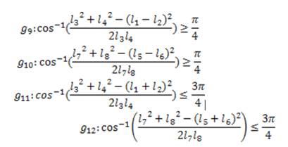
and  satisfy the Grashof criterion, which mentions that given a 4-link mechanism there is at least one complete revolution joint (link 2). The inequalities that describe this behavior are presented in Equation 9 for the submechanism
  and in Equation 10 for the submechanism
  .
.
5.4. Movement transmission quality
The quality of motion transmission is a measure that allows us to ensure the efficiency with which movement is transmitted in a mechanism. For 4-link mechanism  and
and  , the ideal transition angle
  and
and  it is
it is  , with this value it is ensured that there is the greatest force transmission of the output link. In practice it is observed that the transmission angle is not kept constant due to the movement of the crank, therefore to guarantee a good transmission of movement it is considered that the angle of transmission is between the range
  (Balli and Chand, 2002). The restrictions that satisfy this property are defined by Equation 11.
For the 5 links mechanism it is desired that the movement transmission be the maximum at the point  It is also known that the maximum transmission of force is exerted when the angle
  formed by the links
  and
and  is between
  (Balli and Chand, 2002), for any angle of crank, therefore the restrictions to satisfy are in Equation 12.
5.5. Links constraints
To maintain the morphology of the link in Figure 2, it is necessary to include constraints in the problem that limit its design variables. Therefore the constraints necessary to preserve the link morphology are presented in Equations 13 and 14. Where  is the minimum allowable distance between the edges of the holes.
If  add the following constraints:
5.6. Drill holes restrictions
This restriction has the purpose of ensuring that the drill holes are within in the area of the link. To satisfy this characteristic, the constraints presented in Equation 15 are included. Where  represents the minimum allowable distance measured from the edge of the hole to the edge of the link
  represents the coordinate of the center of the hole, and the parameters
 are the design parameters of the link of the Figure 2.
5.7 System dynamics
The dynamics of the system is a restriction that governs the behavior of the system in terms of the forces that interact in it, and allows us to obtain information about the torque of the mechanism and the internal forces in the links.
To obtain the dynamics of the mechanism, Newton's method is used for the analysis of forces and pairs. The equations that define this method are presented in Equation 16 where  is the force present in the link pin,
  is the moment of inertia measured from the center of mass,
 corresponds to the inertial tensor on the axis
  measured from the center of mass,
  , is the linear acceleration at the center of mass,
  is the angular acceleration,
  is the mass of the link and the subscript
  indicates the link in study.
Equation 16 form a system of equations, for this mechanism of 8 links the system of equations has 21 equations and 21 unknowns, where the unknowns corresponding to the torque  and the forces present in the link pins. In a compact form, the dynamic model can be represented as shown in Equation 17, where
  is a relation that maps the design parameters
  , to find the torque
  .
.
In this work the dynamic parameters of the mechanism are determined by the morphological configuration of the links, which are defined as hexagonal links as shown in Figure 2. Where the dynamic properties are defined from longitudinal variables , the diameter of the holes
  and the density of the material
  . To define the dynamic parameters of this link, is used the analysis methodology presented in (Villarreal-Cervantes et al., 2010).
6. Optimization
To solve this optimization problem, the Diferential Evolution (ED) algorithm is used. This algorithm belongs to the classification of evolutionary algorithms and is a stochastic direct search method. The first article related to this algorithm is the technical report developed by R. Storn and K. V. Price in 1995 (Storn, 1995).
ED has been used to solve a great variety of problems of optimization for engineering, because it presents a good approximation to the solution in a reasonable time, it is also simple to understand and implement, and has few parameters to tune. For the solution of the optimization problem planned in this work, the ED algorithm is used in its variant ED/RAND/1/BIN.
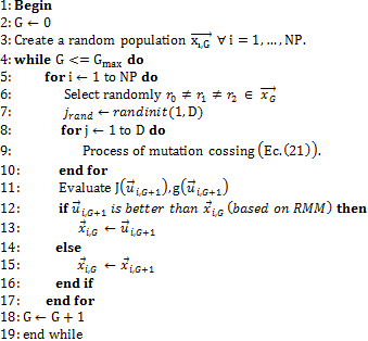
The ED algorithm consists of four processes: initialization, mutation, crossing and selection. The algorithm is described in Figure 3.
In the Equation 20, the mutation process is presented, where F is the scale factor considered in the interval  , this factor has the purpose of avoiding stagnation
in the search process. The selection of individuals  , is defined in a pseudo-random way.
In the Equation 21, the crossing process is presented, where the recombination factor CR exists in the interval [0,1], and is a constant value. If is considered a CR < 0.5, it indicates that the parameters of the parent vector ( ) are more likely to be selected than that of the son vector
  and vice versa.
6.1. Restriction management mechanism (RMM)
The criteria for the selection of individuals is based on Deb's restrictions management mechanism (Mezura-Montes et al., 2004), which establishes the following:
Any feasible solution is preferred with respect to an infeasible.
Between two feasible solutions, the one with the best objective function present is preferred.
Of two non-feasible solutions, the one with the least number of restrictions is preferred.
7. Experimentation
To obtain the solution to the optimization problem, 50runs of the algorithm were performed, considering the crossing factor CR = 0.6. In each run we propose a population NP = 20 of individuals and a maximum of generations Gmax = 200000, in addition the weights of the objective function are established in the following way  , and
, and 
As mechanical conditions, the following is considered:
The material of the links is aluminum 6061-O which has a density of  .
.
The diameter of the drill holes  are constant for each link with a value of
  .
.
The minimum allowable distances  and
and  are equal to the diameter
  .
.
The speed of the crank  is constant and has a value of 60 RPM.
As biomechanical conditions of the trajectory, the following is considered:
The step time is established from the speed of the crank  that is, it will have one step per revolution of the crank
It is considered that the time in the support phase is 60% of the length of the step, therefore it must be  , and consequently
  .
.
The force exerted on the final vector is considered constant on the  axis with a value of -9.81 N and represents the weight exerted by the leg when the user is seated.
For algorithm implementation software MATLAB®, is used in a desktop computer with Windows 10 ® which has an Intel® CoreTM processor i7 @ 3.50GHz and 16GB in RAM. In this computer it was obtained that the average time of each run is 1.5 h.
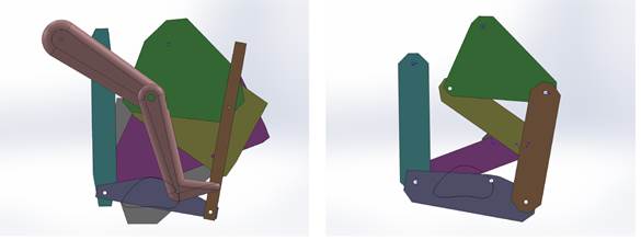
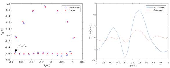
In Figure 4(a) the mechanism obtained in the best run is shown. As shown in Figure 5(a) the trajectory obtained by the mechanism tends to follow the desired path, and this presents a path error of  , so it is considered that the mechanism grants viable path for a rehabilitation routine.
To show the optimized performance of this mechanism comparison is performed with respect to the mechanism of the Figure 4(b), which has the same trajectory as the optimized mechanism but is not considered the torque in the design of its links. In Figure 5(b) shows the graph of the performance of the torque of both mechanisms, in which it is observed that the mechanism that presents a better performance is the obtained in the optimization process and which has an improvement of the 78% compared to the non-optimized.
In order to know the behavior of the objective function, a statistical analysis of the performance of the objective function is performed in the 50 runs, as statistical data the mean, the standard deviation, the median and the maximum and minimum values of the objective function are calculated. The statistical results are shown in Table 1.
From the statistical data in Table 1, it is observed that the values of the mean and the median are different, which indicates that the solutions tend to converge to local minimums. Because the values of the standard deviation and the difference between the maximum and minimum value of the objective function are different from zero, it is concluded that the objective function is multimodal.
8. Conclusions
In this paper, we present the mechanical design of a rehabilitation mechanism based on the approach and solution of an optimization problem, in which dimensional synthesis is considered and the torque is minimized to facilitate control. According to the results obtained, the following is concluded:
In this work it is shown that when a mechanism is designed concurrently a better performance of energy consumption is obtained compared to a conventional design.
When considering the behavior of the motor torque in the optimization problem, it is possible to obtain a mechanical structure that facilitates the control and minimizes the energy consumption.
The algorithm of Differential Evolution in its variant RAND/1/BIN presented satisfactory results since it was possible to satisfy the planned objectives in the optimization problem.
In practice it was observed that when approach the optimization problem through the weighted sums method, it is possible to obtain good results, as long as the weighting of the trajectory error is greater than that of the motor torque.
According to the results obtained, it is concluded that the mechanism of 8 links presented in this article, has the capacity to grant training routines for rehabilitation for lower limbs, since the trajectory obtained by the mechanism has an error of  , with respect to the objective trajectory.
As a future work will include restrictions of axial forces for the links, with the purpose of avoid mechanical failures due to the forces present in the mechanism


